Air conditioner for automobile
a technology for air conditioners and automobiles, applied in the direction of domestic cooling devices, lighting and heating devices, electric propulsion mountings, etc., can solve the problems of insufficient cooling wind amount, complex shape of ducts forming air flow paths, and low heat exchange efficiency
- Summary
- Abstract
- Description
- Claims
- Application Information
AI Technical Summary
Benefits of technology
Problems solved by technology
Method used
Image
Examples
second embodiment
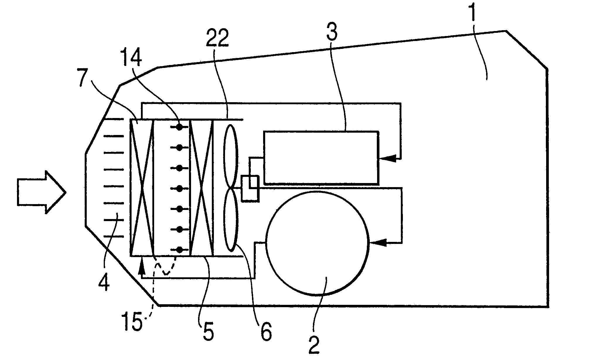
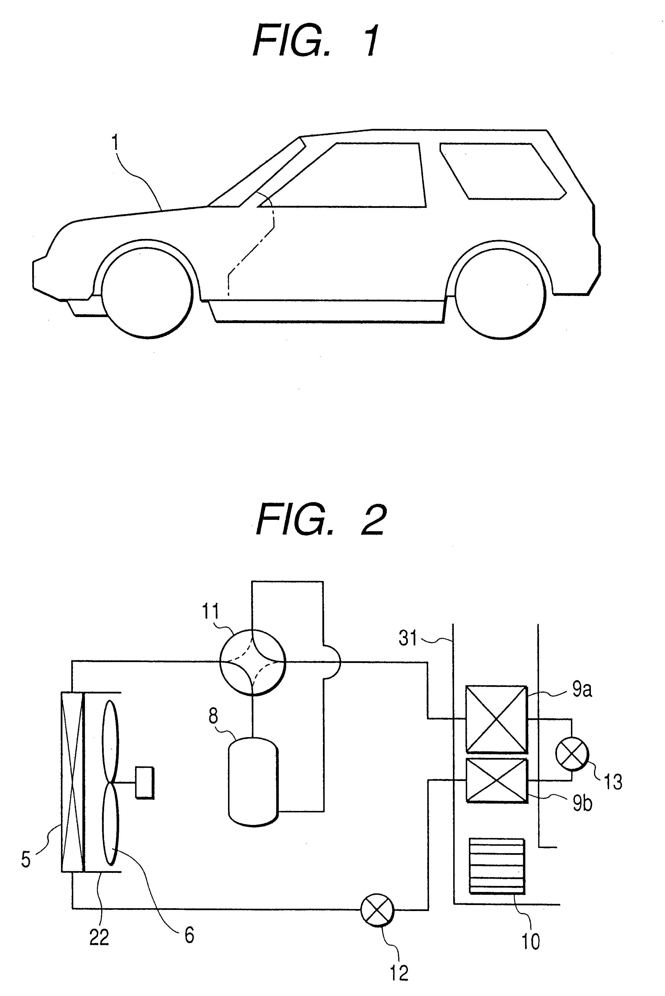
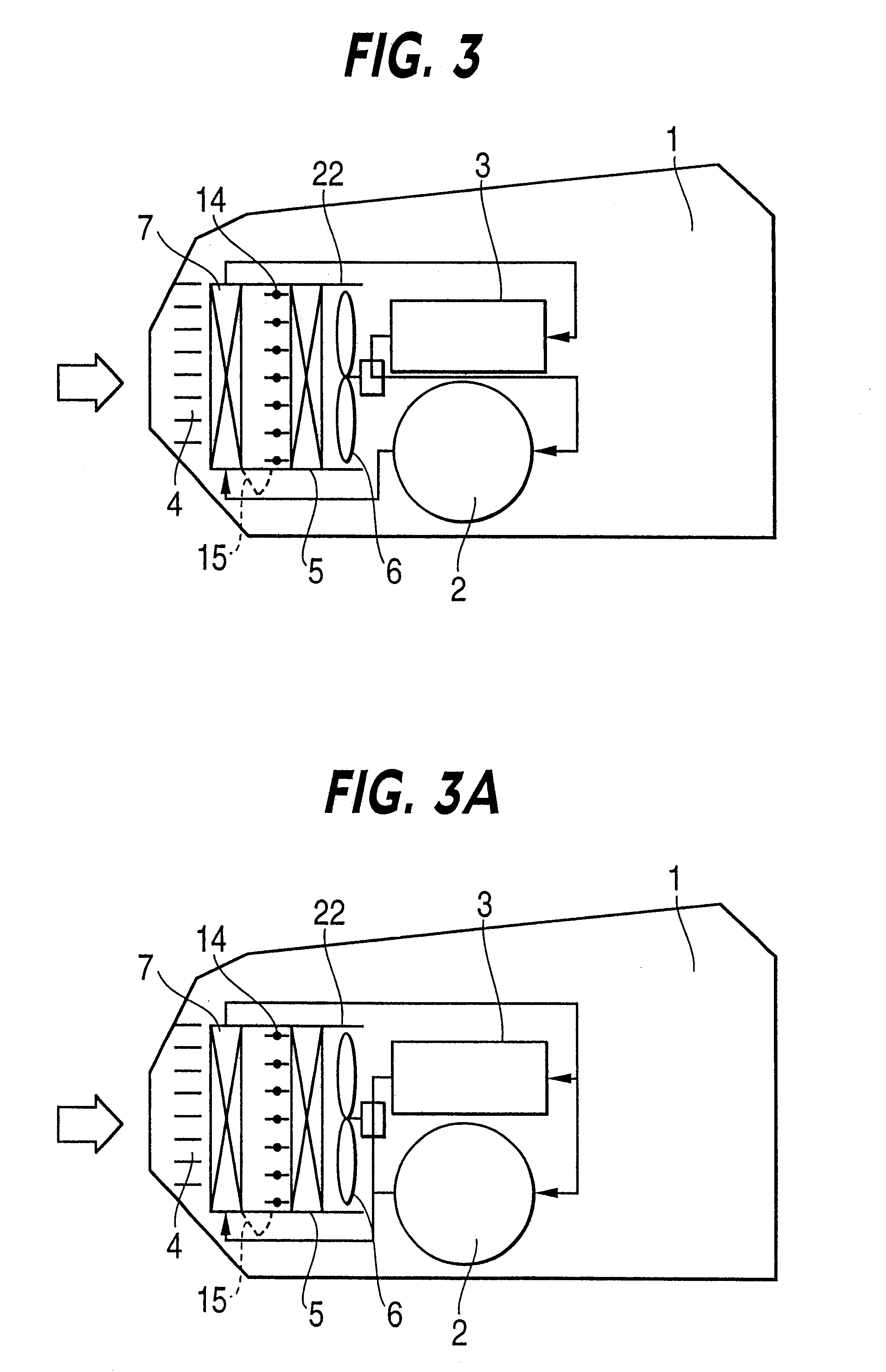
As shown by FIG. 6, a damper 16 and the exterior heat exchanger 5 are arranged in the first duct 24 and the radiator 7 and a damper 17 are arranged in a second duct 25. The two ducts 24 and 25 are contiguously provided in parallel with each other, inlet sides thereof connect to the outside air introducing grille 4 and the two ducts are provided to extend from the outside air introducing grille 4 to a rear side in the motor chamber 1. The damper 16 is provided to open and close an air flow path on the inlet side of wind blowing of the exterior heat exchanger 5 and is constituted by a plurality of sheets. A damper 17 is provided to open and close an air flow path on an outlet side of the radiator 7 and is constituted by a plurality of sheets. A path (inlet side path of the exterior heat exchanger 5) at a middle portion of the damper 16 and the exterior heat exchanger 5 and a path (outlet side path of the radiator 7) at a middle portion of the radiator 7 and the damper 17, are connecte...
first embodiment
In heating operation, the dampers 16 and 17 are closed and the damper 18 is opened. Thereby, outside air is inhale to the duct 25, heated by the radiator 7 and thereafter guided to the duct 24 via the damper 18 and introduced into the exterior heat exchanger 5. Thereby, waste heat of the electric apparatus can effectively be recovered to utilize and an effect the same as that of the above-described first embodiment is achieved.
Further, when rain or snow falls, outside air reaches the exterior heat exchanger 5 via the radiator 7 and therefore, rain or snow precipitates here and does not reach the exterior heat exchanger 5. Thereby, an effect the same as that of the above-described first embodiment is achieved.
In defrosting of heating operation, the damper 16 and the damper 18 are closed, the damper 17 is opened and the exterior fan 6 is stopped. Thereby, flow of air at the surrounding of the exterior heat exchanger 5 is stopped and accordingly, heat used for defrosting does not leak ...
third embodiment
Here, an explanation will be given of a modified example of the third embodiment in reference to FIG. 9. According to the modified example shown in FIG. 9, the ducts 26 and 27 arranged with the damper 19, the exterior heat exchanger 5, the radiator 7 and the exterior fan 6, are arranged at a rear portion of the motor chamber 1 and on rear sides of the driving motor 2 and the motor driving power source 3. When rain or snow falls in heating operation, according to the embodiment shown in FIG. 8, rain or snow reaches the exterior heat exchanger 5 and attachment of frost or attachment of ice is caused and therefore, the above-described defrosting operation is needed frequently to ensure the heating capacity. When the exterior heat exchanger 5 is arranged on the rear side of the motor chamber 1 as shown by the modified example, outside air reaches the outside air heat exchanger 5 at a constant distance from the intake port 4 and therefore, during the time period, rain or snow precipitate...
PUM
 Abstract
Description
Claims
Application Information
 - R&D
- Intellectual Property
- Life Sciences
- Materials
- Tech Scout
- Unparalleled Data Quality
- Higher Quality Content
- 60% Fewer Hallucinations
Browse by: Latest US Patents, China's latest patents, Technical Efficacy Thesaurus, Application Domain, Technology Topic, Popular Technical Reports.
© 2025 PatSnap. All rights reserved.Legal|Privacy policy|Modern Slavery Act Transparency Statement|Sitemap|About US| Contact US: help@patsnap.com


