flow adjustment valve

A technology of flow adjustment valve and flow change, applied in the direction of valve lift, valve details, valve device, etc., can solve the problems of obstructed flow, noise, large pressure loss, etc., and achieve the effect of reducing pressure loss and reducing noise

Active Publication Date: 2020-11-20
FUJIKOKI MFG CO LTD
View PDF2 Cites 0 Cited by
  • Summary
  • Abstract
  • Description
  • Claims
  • Application Information

AI Technical Summary

Problems solved by technology

[0003] However, when the flow regulating valve with the above-mentioned structure is combined with, for example, a heat pump type cooling and heating system, there is a problem that the refrigerant flowing into the valve chamber will not be able to flow until the valve port is opened to a predetermined opening degree. When flowing out from the valve chamber through the gap formed between the valve core and the valve port, it is easy to generate continuous noise (fluid passing sound)
However, the noise-absorbing member is fixed to the valve main body so as to always separate the inlet side and the outlet side of the valve chamber. Therefore, there is the following problem in the large opening area where the flow rate through the valve port needs to be ensured. : The flow of fluid to the valve port is hindered, the pressure loss (pressure loss) increases, and it is difficult to obtain a suitable refrigerant flow rate

Method used


Image

  • flow adjustment valve
  • flow adjustment valve
  • flow adjustment valve

Examples


no. 1 approach

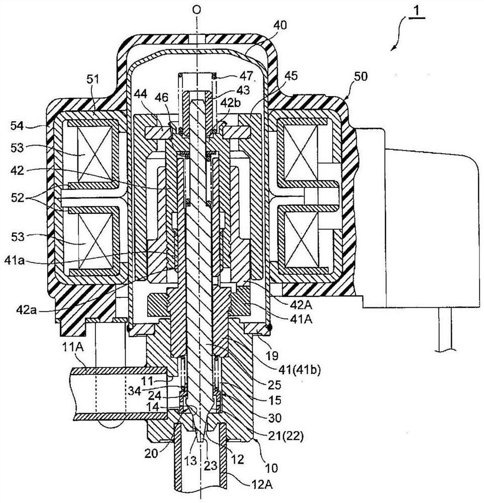
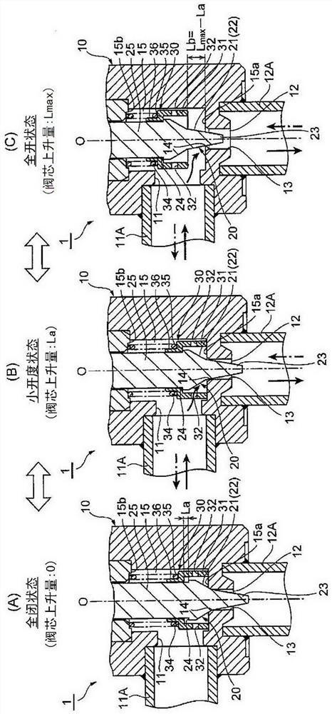
[0065] figure 1 is an overall cross-sectional view showing the first embodiment of the flow regulating valve according to the present invention, figure 2 It is a sectional view of main parts showing the main parts of the flow rate regulating valve according to the present invention in the first embodiment, figure 2 (A) is a diagram showing a fully closed state, figure 2 (B) is a diagram showing a state where the valve opening is small, figure 2 (C) is a diagram showing a fully opened state.

[0066] The flow rate regulating valve 1 of the illustrated embodiment is an electric valve for adjusting the flow rate of refrigerant used in, for example, a heat pump refrigeration and heating system. It is the same as the above-mentioned conventional electric valve. Basically, the flow rate regulating valve 1 has The valve main body 10 and the valve core 20, the valve main body 10 has a valve chamber 15 for introducing and exporting fluid (refrigerant) and a valve port 13 with a ...

no. 2 approach

[0086] Figure 4 It is a sectional view of main parts showing the main parts in the second embodiment of the flow rate regulating valve according to the present invention, Figure 4 (A) is a diagram showing a fully closed state, Figure 4 (B) is a diagram showing a state where the valve opening is small, Figure 4 (C) is a diagram showing a fully opened state.

[0087] Basically, the structure of the noise reduction member 30 of the flow rate adjustment valve 2 of the second embodiment is different from the flow rate adjustment valve 1 of the above-mentioned first embodiment. Therefore, components having the same functions as those in the first embodiment are given the same reference numerals and their detailed descriptions are omitted, and only the points of difference will be described in detail below.

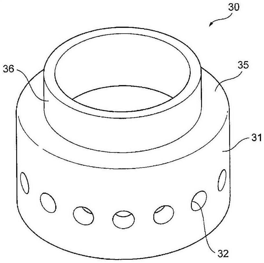
[0088] In the flow rate regulating valve 2 of this embodiment, the cylindrical body 31 and the cover body 35 constituting the noise reduction member 30 are formed as sepa...

no. 3 approach

[0098] Figure 5 is a cross-sectional view of main parts showing a third embodiment of a flow rate regulating valve according to the present invention, Figure 5 (A) is a diagram showing a fully closed state, Figure 5 (B) is a diagram showing a state where the valve opening is small, Figure 5 (C) is a diagram showing a fully opened state.

[0099] Basically, the flow rate control valve 3 of the third embodiment is different in structure surrounding the valve port 13 from the flow rate control valve 2 of the second embodiment described above. Therefore, components having the same functions as those in the second embodiment are assigned the same reference numerals and their detailed descriptions are omitted, and only the points of difference will be described in detail below.

[0100] In the flow control valve 3 of the present embodiment, the cylindrical body 31 and the lid body 35 constituting the noise reduction member 30 are removed, and the compression coil spring 34 bi...


PUM


Abstract

The invention provides a flow control valve capable of effectively reducing noise when a fluid (refrigerant) passes through and reducing a pressure loss in a large opening degree region. In the flow control valve, a sound deadening member (30) for subdividing bubbles in a fluid is disposed in a valve chamber (15) so as to surround a valve port (13), and when the flow rate of the fluid flowing into the valve port (13) increases, a flow path of a predetermined width Lb not passing through the sound deadening member (30) is formed around the valve port (13) in the valve chamber (15).

Description

technical field [0001] The invention relates to a flow regulating valve suitable for adjusting refrigerant flow in heat pump refrigeration and heating systems, and in particular to a flow regulating valve capable of reducing noise when fluid (refrigerant) passes through. Background technique [0002] As an example of such a flow control valve, an electric valve is known, which includes a valve main body and a valve core. The valve main body is provided with a valve chamber and a valve seat with a valve port (orifice). The flow rate of the fluid flowing through the valve port changes, and the valve core passes through a valve shaft with a male thread, a guide rod with a female thread, and a stepping motor as described in Patent Document 1. The screw feed type lifting drive mechanism composed of the valve seat can be lifted in a manner of contacting and separating from the valve seat or approaching and moving away. [0003] However, when the flow regulating valve with the abo...

Claims


Application Information

Patent Timeline
Patent Type & Authority Patents(China)
IPC IPC(8): F16K31/04F16K47/02F16K1/32
CPCF16K1/32F16K31/04F16K47/02
Inventor 原田贵雄柳泽秀
Owner FUJIKOKI MFG CO LTD
Why Eureka
Try Eureka