Connector adapting structure

A connector, elastic contact technology, applied in the direction of connection, parts of the connection device, contact parts, etc., can solve the problems of user inconvenience, structural damage, waste, etc.

Inactive Publication Date: 2017-07-28
KUANG YING COMPUTER EQUIP CO LTD
View PDF7 Cites 2 Cited by
  • Summary
  • Abstract
  • Description
  • Claims
  • Application Information

AI Technical Summary

Problems solved by technology

[0002] According to, as time changes, electronic products are constantly updated and improved, but for a company, the constant replacement of new electronic product equipment will also increase the company's cost, and the old electronic product equipment only fails to meet the requirements in a certain field. However, the same effect as new electronic equipment can be achieved through a conversion connector, and there is no need to replace it to cause unnecessary waste. This concept brings new business opportunities to connector manufacturers.
[0003] In addition, the known USB connector includes an insulating body and several terminals arranged on the insulating body. When the connector and the mating connector are inserted into each other, the correct (positive insertion) direction must be maintained. If the connector is not If it is inserted carefully, it will not be able to be inserted smoothly, and the plugging action must be performed again, which may even cause structural damage and cause inconvenience to users
[0004] Although there are many patents on the connectors that can be plugged in the front and back, there are already products in the market, whether it is a SIM card, a memory card or a USB connector of various specifications, these connectors can It is not new to make it into a front and back plug. Then, it is used to change the connector specification for the adapter corresponding to the male or female socket to be connected. It is not seen at both ends of the adapter , while designed to allow positive and negative connectors

Method used


Image

  • Connector adapting structure
  • Connector adapting structure
  • Connector adapting structure

Examples


Embodiment Construction

[0052] In order to achieve the above-mentioned purpose and effect, the technical means and the structure adopted by the present invention are hereby described in detail with respect to the preferred embodiments of the present invention.

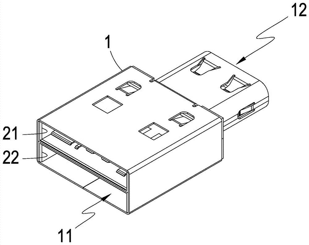
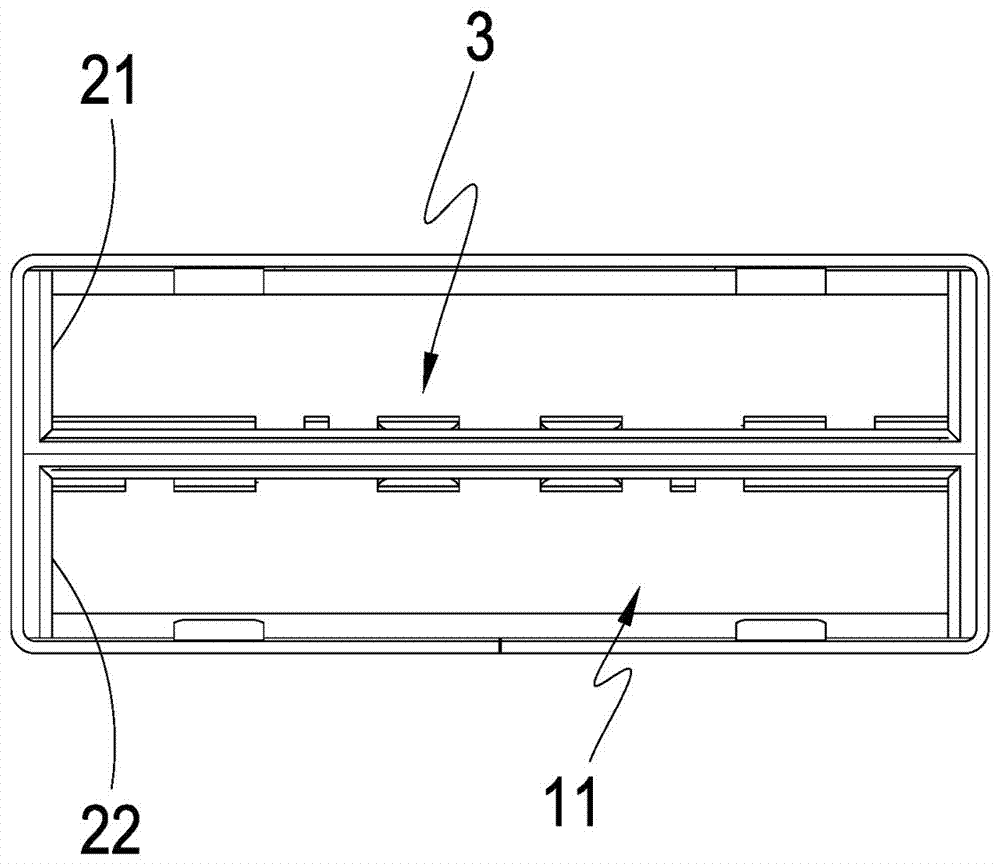
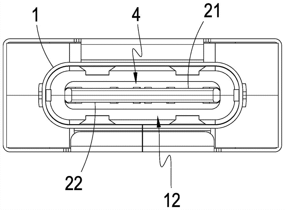
[0053] see figure 1 , figure 2 , image 3 and Figure 4 As shown, it is a perspective view, a front view, a rear view and a perspective view of the second transmission conductor group of a preferred embodiment of the present invention. It can be clearly seen that the present invention includes:

[0054] A shielding shell 1, the shielding shell 1 includes a male end opening 11, and a female seat opening 12 whose opening direction is away from the male end opening 11;

[0055] a first insulating colloid 21 accommodated in the shielding shell 1;

[0056] a second insulating colloid 22 accommodated in the shielding shell 1 and located on one side of the first insulating colloid 21;

[0057] a plurality of first transmission conductor groups...


PUM


Abstract

The invention relates to a connector adapting structure which mainly comprises a shielding housing. The shielding housing comprises a male-end opening and a female base opening of which the opening direction is deviated from that of the male-end opening. Furthermore a first insulating colloid member and a second insulating colloid member at one side of the first insulating colloid member are accommodated in the shielding housing. Furthermore the first insulating colloid member and the second insulating colloid member are provided with a plurality of first transmission conductor sets for forward insertion and backward insertion at the side of the male-end opening. Furthermore the first insulating colloid member and the second insulating colloid member are provided with a plurality of second transmission conductor sets for forward insertion and backward insertion at the side of the female base opening. By means of the connector adapting structure and the integrally formed shielding housing, the first transmission conductor sets and the second transmission conductor sets are simultaneously accommodated, thereby realizing bidirectional forward insertion and backward insertion of the connector at both ends.

Description

technical field [0001] The present invention provides a connector transfer structure, especially a connector transfer structure that uses a single shell to manufacture male-female connectors of different specifications, and allows double-headed bidirectional reciprocal insertion. Background technique [0002] According to, as time changes, electronic products are constantly updated and improved, but for a company, the constant replacement of new electronic product equipment will also increase the cost of the company, and the old electronic product equipment only fails to meet the requirements in a certain field. However, the same effect as that of new electronic equipment can be achieved through a conversion connector, and there is no need to replace it to cause unnecessary waste. This concept brings new business opportunities to connector manufacturers. [0003] In addition, the known USB connector includes an insulating body and several terminals arranged on the insulating...

Claims


Application Information

Patent Timeline
IPC IPC(8): H01R31/06H01R13/02H01R13/502
CPCH01R31/06H01R13/02H01R13/502
Inventor 钟轩禾林昱宏
Owner KUANG YING COMPUTER EQUIP CO LTD
Why Eureka
Try Eureka