
Power supply equipment

A technology for power supply equipment and power supply devices, applied in electrical components, substation/switch layout details, etc., can solve the problems of equipment power failure, low safety factor, inconvenient handling, etc., to facilitate movement and handling, improve safety, power supply good effect

Active Publication Date: 2017-07-28
JIANGSU XIYI HIGH NEW DISTRICT TECH DEV CO LTD
View PDF4 Cites 0 Cited by
  • Summary
  • Abstract
  • Description
  • Claims
  • Application Information

AI Technical Summary

Problems solved by technology

[0002] In daily life, temporary power outages of equipment caused by accidents often occur, which seriously affect production and people's lives. Therefore, emergency power supply equipment is needed to supply power to the equipment. The existing power supply equipment is generally heavy and inconvenient to carry. High price, narrow scope of application, low safety factor, low degree of automation

Method used


Image

  • Power supply equipment
  • Power supply equipment
  • Power supply equipment

Examples


Embodiment Construction

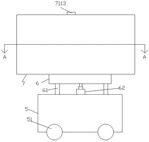
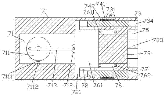
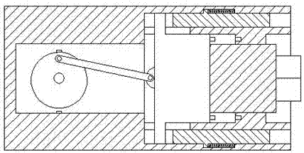
[0021] Such as Figure 1-Figure 5 As shown, a power supply device of the present invention includes a base 5 and a power supply device 7 arranged above the base 5 , the right side of the power supply device 7 is provided with an implementation slot 73 , and inside the implementation slot 73 There is a protruding and sliding part 77 fixedly connected to the inner wall of the left side of the implementation groove 73 on the left side. The left side of the protruding and sliding part 77 is provided with a transmission chamber 76 extending left and right. The right side of the protruding and sliding part 77 is A sinking groove 75 is arranged in the surface, a dividing plate 771 is arranged between the left end of the sinking groove 75 and the right end of the transmission chamber 76, and a right end and the inside of the convex sliding part 77 are arranged inside the left side of the power supply device 7. The left end of the transmission cavity 76 is provided with a continuous ca...


PUM


Abstract

The invention discloses a piece of power supply equipment, which comprises a base and a power supply device arranged at the upper part of the base. The right side face of the power supply device is provided therein with an implementation groove. The implementation groove is provided therein with a protruded sliding part whose left side face is in fixed connection with the inner wall of the left side of the implementation groove. The inner part at the left side of the protruded sliding part is provided with a transmission cavity whose left and right extend. The right side face of the protruded sliding face is provided therein with a sinking groove. Between the left end of the sinking groove and the right end of the transmission cavity, a segment plate is arranged. The inner part at the left side of the power supply device is provided with a cavity part whose right end is connected with the left end of the transmission cavity in the protruded sliding part. The cavity part is provided therein with a rotation wheel. The front inner wall and the back inner wall of the transmission cavity opposite to one side of the segment plate are provided with through holes in communication with the implementation groove. The outer part of the protruded sliding part is provided with a first sliding sleeve. The power supply equipment of the invention has a simple structure and can be conveniently moved and transported for power supply work. Secure in performance, the equipment also achieves a good power supply effect.

Description

technical field [0001] The invention relates to the technical field of power supply, in particular to a power supply device. Background technique [0002] In daily life, temporary power outages of equipment caused by accidents often occur, which seriously affect production and people's lives. Therefore, emergency power supply equipment is needed to supply power to the equipment. The existing power supply equipment is generally heavy and inconvenient to carry. The price is high, the scope of application is narrow, the safety factor is low, and the degree of automation is low. Contents of the invention [0003] The technical problem to be solved by the present invention is to provide a power supply device, which can solve the above-mentioned problems in the prior art. [0004] The present invention is achieved through the following technical proposals: a power supply device of the present invention includes a base and a power supply device arranged above the base, an implem...

Claims


Application Information

Patent Timeline
Patent Type & Authority Applications(China)
IPC IPC(8): H02B1/52
CPCH02B1/52
Inventor 胡龙
Owner JIANGSU XIYI HIGH NEW DISTRICT TECH DEV CO LTD
Learn More