Link detecting method and link detecting device

A link detection and link technology, applied in the field of communication, can solve the problems of insufficiency, large data flow, affecting the performance and efficiency of the controller, and achieve the effect of overcoming the slow detection speed and reducing the high load

Inactive Publication Date: 2017-08-01
ZTE CORP
View PDF0 Cites 9 Cited by
  • Summary
  • Abstract
  • Description
  • Claims
  • Application Information

AI Technical Summary

Problems solved by technology

Therefore, when the network fails, the effectiveness of link switching will not be higher than 1s, which is far from meeting the network's requirement that the path switching rate be lower than 100ms.
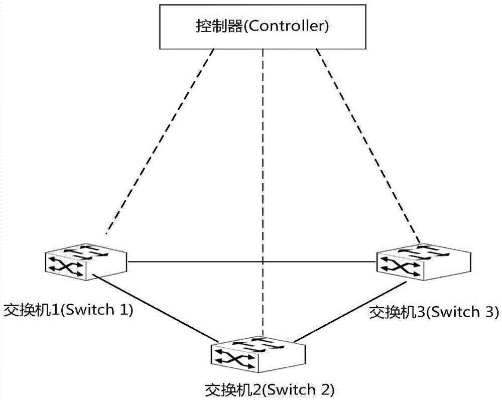
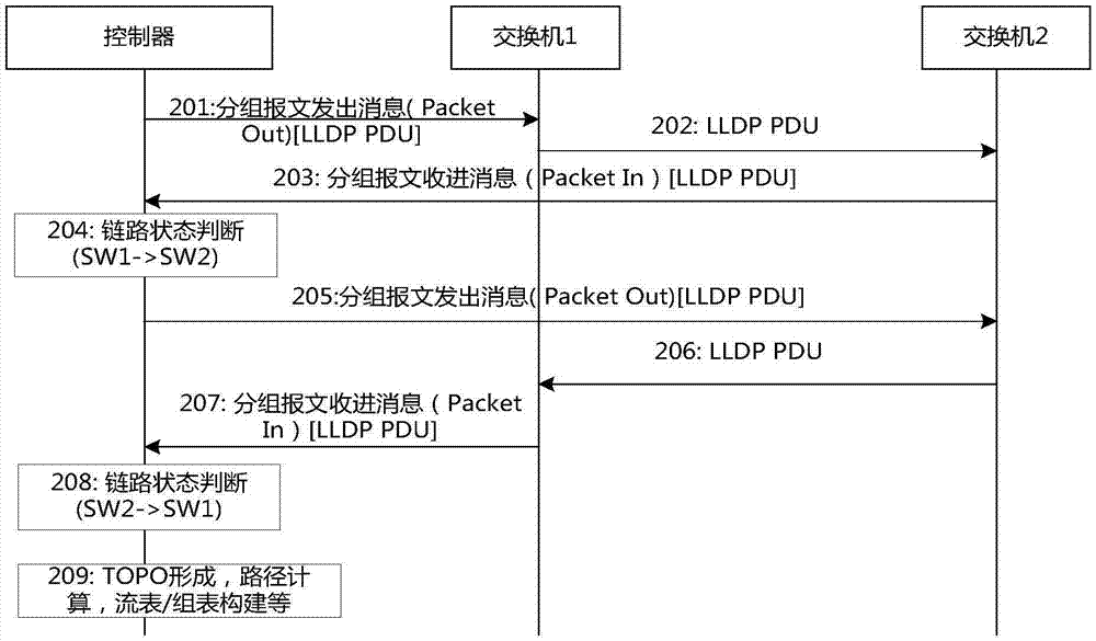
[0014] In addition, each LLDP data packet is generated by the controller and finally sent to the controller for processing. If the detection period of LLDP is set to be very small, the data traffic caused by LLDP packets on the controller will be very large. Causes a large processing burden on the SDN network controller, seriously affecting the performance and efficiency of the controller
[0015] In the related technology, when LLDP is used to detect the link state and detect the link, the timeliness of detecting the link is not high, and it brings a lot of processing burden to the controller, and no effective solution has been proposed.

Method used


Image

  • Link detecting method and link detecting device
  • Link detecting method and link detecting device
  • Link detecting method and link detecting device

Examples


Embodiment 1

[0089] In this preferred embodiment 1, a method for fast link detection is provided, Figure 9 It is a schematic diagram of establishing a session according to the preferred embodiment 1 of the present invention, such as Figure 9 As shown, a BFD management unit is set in the controller, which is called BFDM (BFDManager, BFD management unit) herein.

[0090] Step S902: BFDM sends BFD control messages to the switches SW1 and SW2 through the Netconfig protocol, which are also called configuration parameters, such as BFD start switch, control message time, receiving time interval, session timeout period, management address, etc.

[0091] Step S904: After receiving the BFD configuration parameters, the switches SW1 and SW2 establish a BFD session, and then keep alive the BFD session.

[0092] Among them, the specific mechanism of the keep-alive of the BFD session and the detection of the link is as follows: The BFD session has two modes: the asynchronous mode. Asynchronous mode ...

Embodiment 2

[0112] In preferred embodiment 2 of the present invention, a method for fast link detection is provided, Figure 11 is a schematic diagram of establishing a session according to the second preferred embodiment of the present invention, such as Figure 11 As shown, the BFD management unit BFDM is set in the controller.

[0113] Step S1102: BFDM sends a BFD control packet to the controlled switch SW1 through the Netconfig protocol, which is also called configuration parameters, such as BFD start switch, time interval for receiving control packets, session timeout duration, management address, etc.

[0114] SW2 is an uncontrolled switch, so the BFD parameters will not be obtained through the controller, but are pre-configured on the switch.

[0115] Step S1104: The switch SW1 is configured with parameters. If the corresponding BFD parameters are also configured on SW2, session negotiation will be initiated to establish a BFD session between the two switches. Wherein, the negoti...


PUM


Abstract

The invention provides a link detecting method and a link detecting device. The method comprises steps of generating bidirectional forwarding between switches to detect a BFD session, and receiving a link failure detection result determined by the switch according to the BFD session, wherein the link failure detection result is used for indicating whether the link of a forwarding side has a failure or not. By adopting the above technical scheme of the invention, the problem in related technologies that the timeliness of link detection is poor because LLDP is used for detecting a link state and thus a huge processing load is brought to the controller can be solved, and the problem that the detection speed of LLDP used for detecting links is low is reduced; in addition, as compared with LLDP, BFD session interaction messages involve a small data size, which greatly relieves the problem of high load of the controller.

Description

technical field [0001] The present invention relates to the communication field, in particular to a link detection method and device. Background technique [0002] Software Defined Network (SDN for short) is a hot research technology in the current communication field. The SDN consists of two parts: a controller (Controller, C for short) on the control plane and a switch (Switch, SW or S for short) on the forwarding plane. According to the definition of the current SDN technology, the controller Controller and the switch Switch issue control instructions through the OPENFLOW (abbreviated as OF) protocol to guide the data flow forwarding on the switch; the controller also uses Netconfig (Network Configuration Protocol, network configuration protocol). Perform parameter configuration on the switch SW. Among them, the OF protocol is a forwarding / control separation protocol proposed by Stanford University in the United States in 2008. The external control plane entity uses the...

Claims


Application Information

Patent Timeline
IPC IPC(8): H04L12/24H04L12/26
CPCH04L41/06H04L43/08
Inventor 毕以峰潘云波武晓林周蕙菁李响
Owner ZTE CORP
Why Eureka
Try Eureka