Supercharge Your Innovation With Domain-Expert AI Agents!

Capacitors for multilayer printed circuit boards

A multi-layer printing and capacitor technology, applied in the field of capacitors, can solve problems such as difficult decoupling

Active Publication Date: 2020-01-17
FINISAR
View PDF7 Cites 0 Cited by
  • Summary
  • Abstract
  • Description
  • Claims
  • Application Information

AI Technical Summary

Problems solved by technology

However, decoupling at microwave and terahertz frequencies can be difficult due to parasitic resistance, parasitic inductance, and time to charge and / or discharge the capacitor

Method used


Image

  • Capacitors for multilayer printed circuit boards
  • Capacitors for multilayer printed circuit boards
  • Capacitors for multilayer printed circuit boards

Examples


Embodiment Construction

[0018] Embodiments described herein relate generally to capacitors for printed circuit boards.

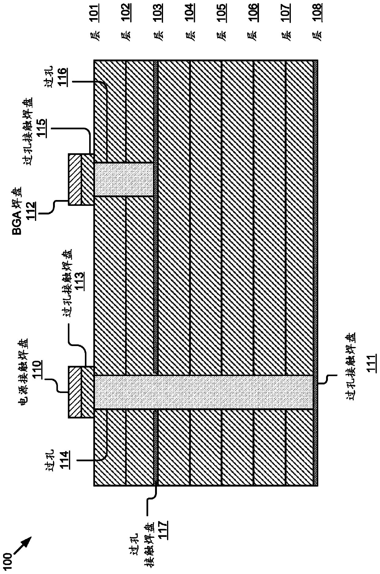
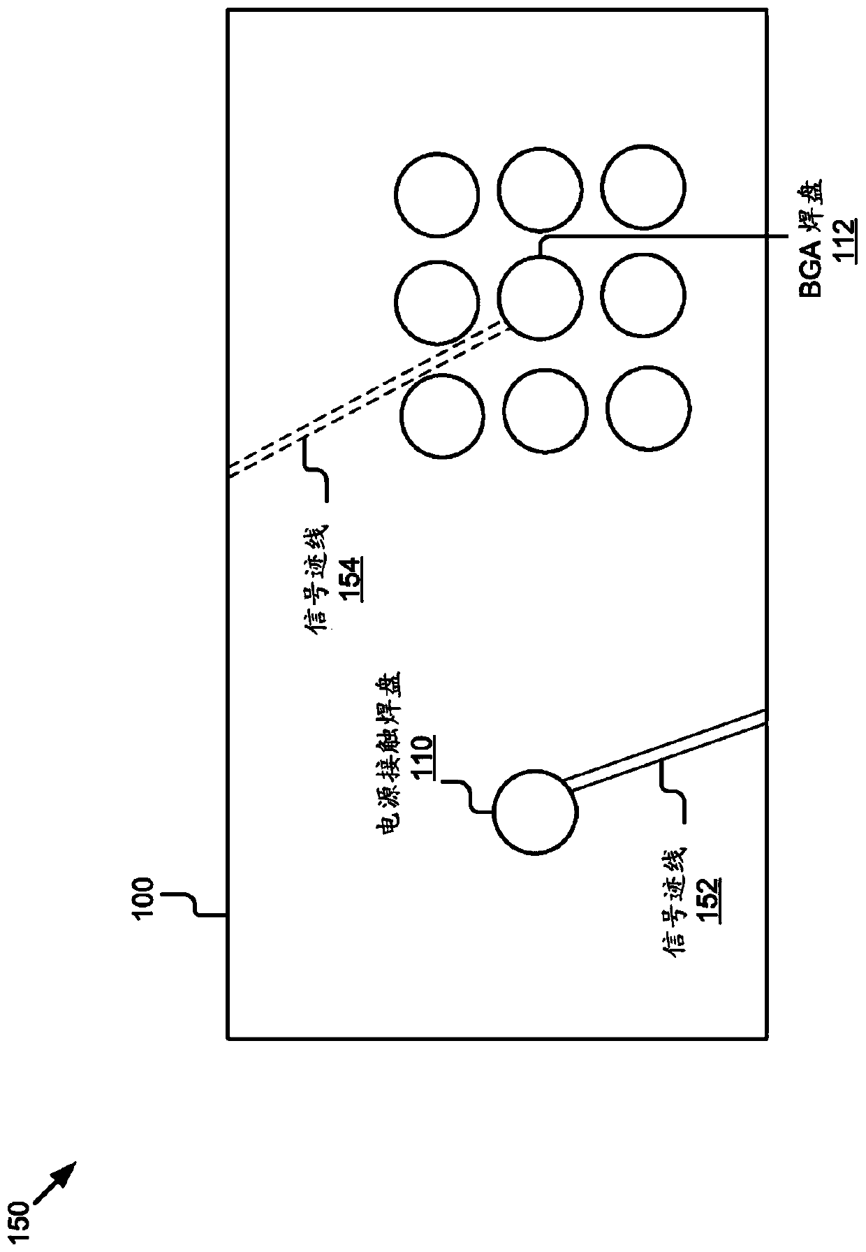
[0019] Some embodiments described herein may include via-in-pad capacitors that may be included in rigid or flex PCBs for high frequency applications. For example, capacitors can be charged and / or discharged quickly and can be implemented in applications at 25GHz or higher. In another example, capacitors may be implemented in 56GHz or higher frequency applications. Under-pad via capacitors can be placed directly below the IC contact nodes, which eliminates contact resistance, reduces ESR and ESL, and eliminates area factor compared to parallel plate capacitors and / or printed capacitors. Via under pad capacitors may have a high self-resonant frequency compared to parallel plate capacitors and / or printed capacitors.

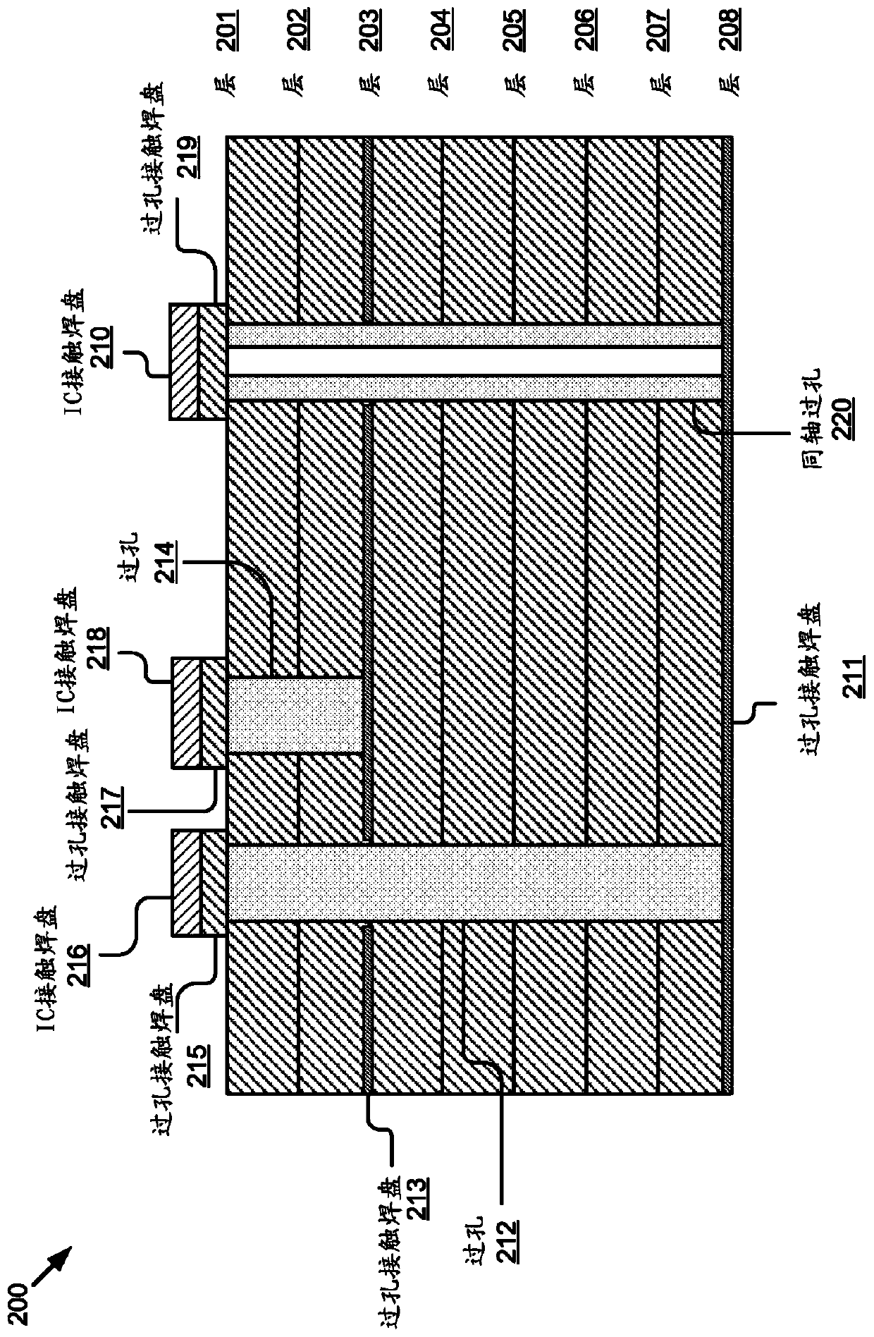
[0020] In some implementations, an under-pad via capacitor may include a via disposed directly under an IC contact pad and a dielectric compound filled in the via. A...


PUM

PropertyMeasurementUnit
sizeaaaaaaaaaa

Abstract

A capacitor in a multilayer printed circuit board (100) is described. The capacitor may include vias (114), (116) of the via-under-pad type and a dielectric compound filled in the via-under-pad type vias. Vias may be provided under integrated circuit contact pads (112) of the multilayer printed circuit board. The dielectric mixture may include nanoparticle-sized dielectric powder mixed with a binder material.

Description

technical field [0001] Some embodiments described herein relate generally to capacitors for high frequency applications. Background technique [0002] Unless otherwise indicated herein, the materials described herein are not prior art to the claims in this application and are not admitted to be prior art by inclusion in this section. [0003] The parasitic resistance (eg, equivalent series resistance (ESR)) and parasitic inductance (eg, equivalent series inductance (ESL)) of capacitors are detrimental to the high frequency performance of integrated circuits (ICs). The capacitance of a parallel plate capacitor can depend on the area occupied by the capacitor in a printed circuit board (PCB). However, space in a PCB is often a scarce resource because many circuit components can be integrated into a PCB. Parallel plate capacitors can often be present on the other side of the PCB where they are connected to vias and / or traces that can introduce additional inductance (eg, ESL) ...

Claims


Application Information

Patent Timeline
Patent Type & Authority Patents(China)
IPC IPC(8): H05K1/16H05K1/02H05K1/11
CPCH05K1/0231H05K1/0243H05K2201/0187H05K2201/09809H05K1/113H05K1/162H05K2201/10734H05K2201/0257H05K1/115H05K1/092H05K1/0298H05K1/182H05K2201/09545
Inventor 亨利·M·达格希吉安
Owner FINISAR
Features
  • R&D
  • Intellectual Property
  • Life Sciences
  • Materials
  • Tech Scout
  • Unparalleled Data Quality
  • Higher Quality Content
  • 60% Fewer Hallucinations
Learn More