Side-drain floor drain

A technology of floor drain and water inlet, applied in drainage structures, waterway systems, water supply devices, etc., can solve problems such as poor deodorization effect

Pending Publication Date: 2017-08-04
HUBEI YIMU SAME FLOOR DRAINING WATER SCI & TECH CO LTD
View PDF7 Cites 0 Cited by
  • Summary
  • Abstract
  • Description
  • Claims
  • Application Information

AI Technical Summary

Problems solved by technology

There are various anti-odor floor drains in the prior art, but their anti-odor effect is poor, and it cannot completely prevent the gas in the drainage system from entering the room.

Method used


Image

  • Side-drain floor drain
  • Side-drain floor drain
  • Side-drain floor drain

Examples


Embodiment 1

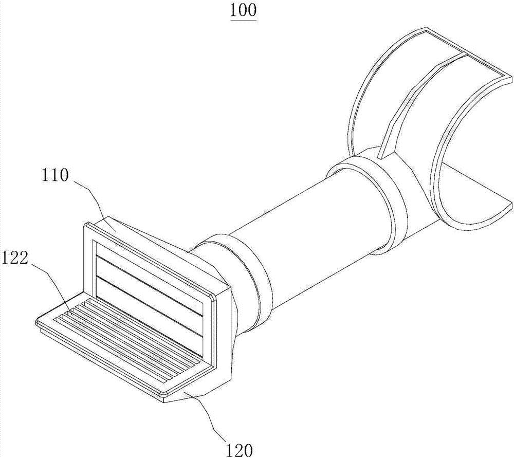
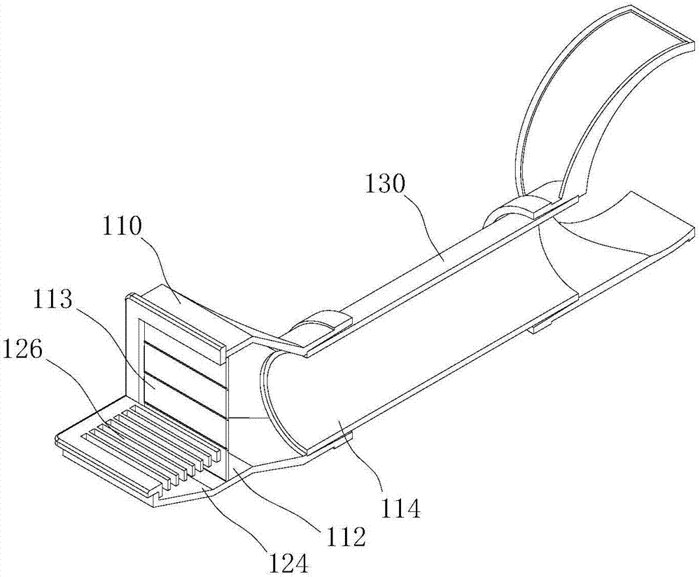
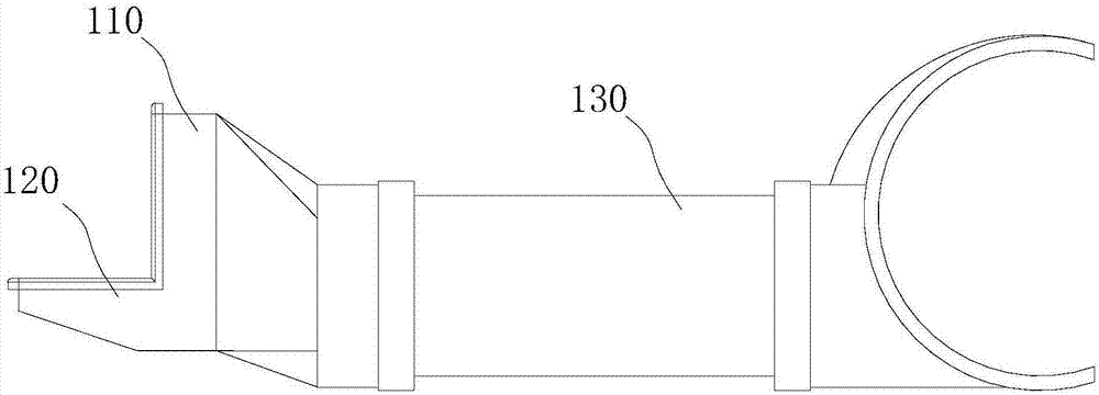
[0054] This embodiment provides a side discharge floor drain 100 for discharging indoor domestic wastewater into a drainage pipe. like figure 1 , figure 2 and image 3 , The side row floor drain 100 mainly includes a first water inlet part 110 and a second water inlet part 120 . The first water inlet part 110 is installed in the wall, and the second water inlet part 120 is installed on the floor. The indoor domestic wastewater reaches the first water inlet 110 through the second water inlet 120, and the first water inlet 110 is connected to the drainage pipe, and the domestic wastewater finally reaches the drainage pipe; when there is too much accumulated water on the ground, the accumulated water will also It can directly enter the floor drain through the second water inlet part 120, and finally reach the drainage pipe.

[0055] like figure 2 , the first water inlet 110 includes a rectangular first water inlet 112 and a circular hole-shaped first water outlet 114; the ...

Embodiment 2

[0069] like Figure 7 , the structure of the side row floor drain 200 in this embodiment is basically the same as that in Embodiment 1, the difference is that the second delivery pipe 240 is added. The angle between the second conveying pipe 240 and the first conveying pipe 130 is set so that the domestic wastewater in the first conveying pipe 130 can enter the second conveying pipe 240 relatively smoothly.

[0070] like Figure 7 , Figure 8 and Figure 9 , the switch door 242 , the fixing plate 244 , the first magnet and the second magnet are arranged in the second conveying pipe 240 . Both the fixed plate 244 and the switch door 242 are semicircular, the fixed plate 244 is arranged on the top of the switch door 242 plate, the two are adjacent to each other, and the switch door 242 is rotatably connected with the second delivery pipe 240 through a rotating shaft. When the switch door 242 is closed, the two together block the second conveying pipe 240 . And the switch do...


PUM


Abstract

The invention provides a side-drain floor drain, belonging to the fields of sanitary appliances and water supply and drainage. The side-drain floor drain is used for draining indoor sanitary wastewater into a draining pipeline. The side-drain floor drain mainly comprises a first water inlet part and a second water inlet part, wherein the first water inlet part is mounted in a wall body, and the second water inlet part is mounted on the floor; and a plurality of rotatable baffles are arranged on the first water inlet part and are used for opening or closing the first water inlet part. The indoor sanitary wastewater enters the second water inlet part, the baffles are opened, the indoor sanitary wastewater reaches the first water inlet part, the first water inlet part is connected with a draining pipeline, and finally, the sanitary wastewater enters the draining pipeline. After the draining is finished, the baffles are automatically closed, so as to block the first water inlet part. The baffles are used to isolate an indoor space from the draining pipeline, and thus the deodorization and the insect prevention can be realized.

Description

technical field [0001] The invention relates to the field of sanitary ware and water supply and drainage, in particular to a side drain floor drain. Background technique [0002] The floor drain is an important interface connecting the drainage system and the indoor ground, and is mainly used to discharge indoor domestic water into the drainage system. With the development of society, if the floor drain can only leak water, it is obviously not conducive to improving people's quality of life. [0003] The floor drain must not only leak water, but more importantly, prevent the gas in the drainage piping system from entering the room through the floor drain. As an important part of the drainage system in the residence, the floor drain directly affects the quality of the air in the bathroom, and then affects people's health. Therefore, the floor drain should also be able to prevent the gas in the drainage system from entering the room, commonly known as "anti-odor". There are...

Claims


Application Information

Patent Timeline
IPC IPC(8): E03F5/04
CPCE03F5/0407E03F2005/0416
Inventor 王超
Owner HUBEI YIMU SAME FLOOR DRAINING WATER SCI & TECH CO LTD
Why Eureka
Try Eureka