Eureka AIR delivers breakthrough ideas for toughest innovation challenges, trusted by R&D personnel around the world.

Pneumatic diaphragm pump with external pneumatic control valve

A technology of pneumatic diaphragm pumps and air control valves, which is applied to pumps with flexible working elements, pumps, machines/engines, etc., can solve the problems of troublesome disassembly and maintenance, high cost, high cost of use, etc., to reduce the number of accessories and use The effect of low cost and simple structure

Inactive Publication Date: 2017-08-04
上海方顿工业设备有限公司
View PDF11 Cites 6 Cited by
  • Summary
  • Abstract
  • Description
  • Claims
  • Application Information

AI Technical Summary

Problems solved by technology

[0003] Most of the pneumatic diaphragm pumps in the prior art control the reversing of the driving gas through the air valve assembly and the built-in reversing valve to control the work of the pneumatic diaphragm pump. high cost

Method used


Image

  • Pneumatic diaphragm pump with external pneumatic control valve
  • Pneumatic diaphragm pump with external pneumatic control valve
  • Pneumatic diaphragm pump with external pneumatic control valve

Examples


specific Embodiment approach

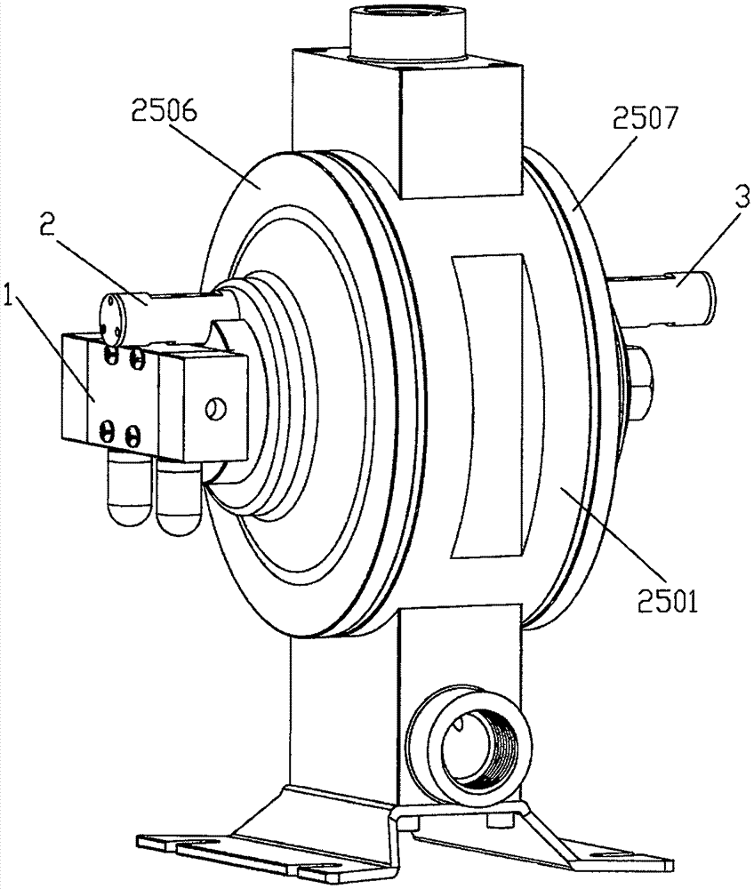
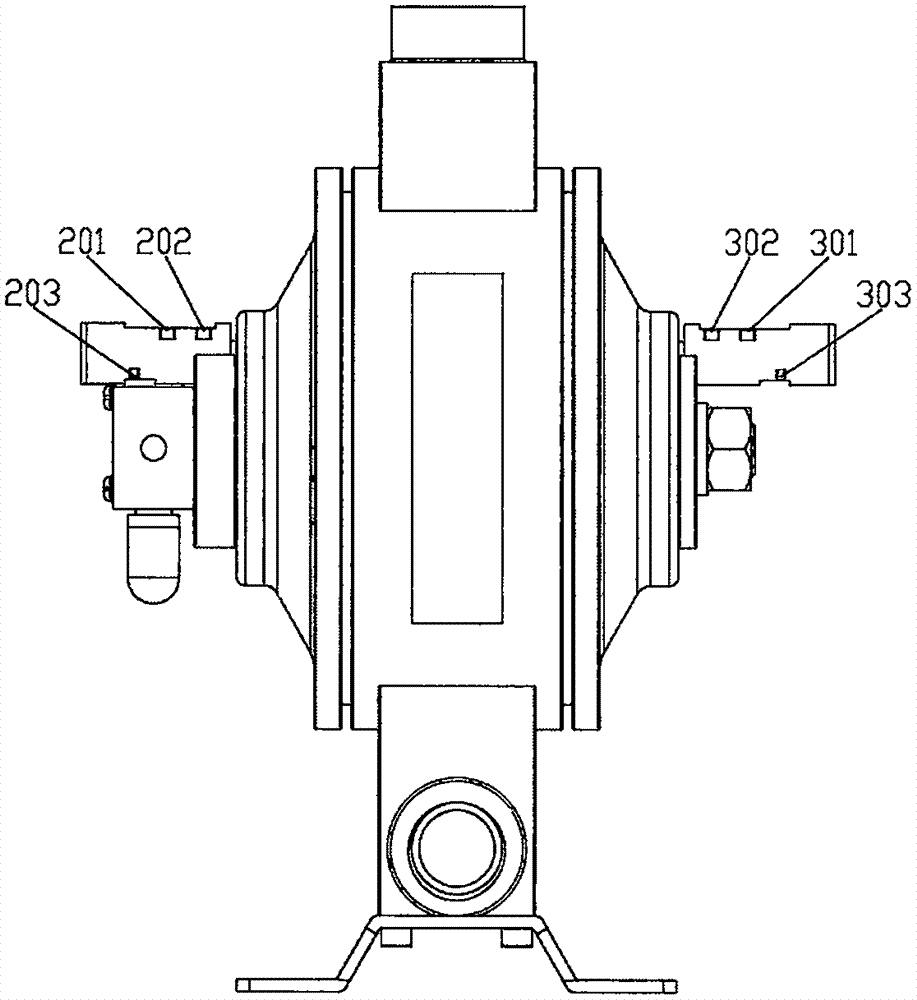
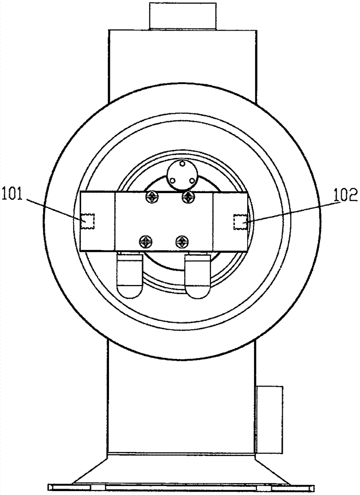
[0019] like Figure 1 to Figure 5 As shown, a pneumatic diaphragm pump with an external air control valve provided by the present invention includes an air control valve 1, a pump body 2501, a central shaft 2517, a left cover 2506, a right cover 2507, a reversing switch 2, and a reversing switch 2 3. There is a U-shaped hole in the center of the pump body 2501, and a diaphragm push rod 2519 is installed in the U-shaped hole to pass through the U-shaped hole across the pump body 2501. The U-shaped hole of the pump body 2501 and A sealing ring 2524 is installed between the diaphragm push rods 2519 to seal the pump body 2501 and the diaphragm push rod 2519; A diaphragm 2516 is respectively installed between the right cover 2507 and the pump body 2501 to divide the left cover 2506, the pump body 2501, and the right cover 2507 into an air cavity and a fluid cavity; The two ends of the push rod 2519 are connected and fixed through the diaphragm inner protection block 2515, the diap...


PUM


Abstract

The invention discloses a pneumatic diaphragm pump with an external pneumatic control valve. The pneumatic diaphragm pump comprises the pneumatic control valve, a pump body, a central shaft, a left cover, a right cover and change-over switches, wherein a U-shaped hole is formed in the center of the pump body; a diaphragm push rod is mounted in the U-shaped hole; the left cover and the right cover are respectively arranged on two sides of the pump body; a diaphragm is mounted between the left cover and the pump body; a diaphragm is mounted between the right cover and the pump body; the centers of the diaphragms on two sides are respectively and fixedly connected with two ends of the diaphragm push rod through diaphragm inner protection blocks, sealing rings and diaphragm outer protection blocks; an external thread is formed in one end of the central shaft; a limiting step is arranged at the other end of the central shaft; the end at which the external thread is formed, of the central shaft, penetrates through a left cover gasket, the left cover, the pump body, the diaphragm push rod, the diaphragms on two sides, and the right cover, and is in fastened connection with the nut; the end at which the limiting step is arranged, of the central shaft, is connected with the pneumatic control valve; an upper cover is connected to the top of the pump body; a lower cover is connected to the bottom of the pump boy; and the change-over switches are respectively mounted on the left cover and the right cover. According to the pneumatic diaphragm pump disclosed by the invention, the pneumatic control valve is arranged outside, so that structure is simple, and application cost is low.

Description

technical field [0001] The invention relates to a pneumatic diaphragm pump. Background technique [0002] Pneumatic diaphragm pump is a new type of conveying machinery, which uses compressed air as the power source. It can be used for various corrosive liquids, liquids with particles, high viscosity, volatile, flammable, highly toxic liquids, and powders. At present, large-scale production has been formed, and the product quality is well received. The main feature of this kind of pump is that it does not need a tank to divert water. It can not only pump flowing liquid, but also transport some difficult-to-flow media. According to many characteristics, it can be divided into plastic pneumatic diaphragm pump and metal pneumatic diaphragm pump. [0003] Most of the pneumatic diaphragm pumps in the prior art control the reversing of the driving gas through the air valve assembly and the built-in reversing valve to control the work of the pneumatic diaphragm pump. high cost. ...

Claims


Application Information

Patent Timeline
Patent Type & Authority Applications(China)
IPC IPC(8): F04B43/073
CPCF04B43/073F04B43/0081
Inventor 刘成新
Owner 上海方顿工业设备有限公司
Why Eureka
Eureka Blog
Learn More