Remote video conference camera supporting equipment with wire fastening function

A technology for remote video and supporting equipment, applied in mechanical equipment, machine/stand, supporting machine, etc., to solve problems such as broken cameras, ripped off from cameras or directly pulled off cameras, obstacles to normal activities of people in conference rooms, etc. , to achieve the effect of saving space

Inactive Publication Date: 2017-08-04
盐城晟远致和信息技术咨询有限公司
View PDF4 Cites 5 Cited by
  • Summary
  • Abstract
  • Description
  • Claims
  • Application Information

AI Technical Summary

Problems solved by technology

Video conferencing can realize multi-party audio and video interaction and is low in cost. Therefore, many enterprises and institutions have assembled their own video conferencing systems. At present, most of the camera fixtures used for video conferencing are tripod devices provided by manufacturers. Although the camera installation It is easy to move on the tripod device, but the tripod device takes up a certain space on the floor of the meeting room, especially for the meeting room where the space is not wide, it is easy to form obstacles to the normal activities of the people in the meeting room, and it is also easy Accidentally knock down the tripod device, break the camera placed on it, and the camera's wiring is exposed outside. When passing people's feet trip over the wiring, it is easy to tear the wiring from the camera or pull the camera directly.

Method used


Image

  • Remote video conference camera supporting equipment with wire fastening function
  • Remote video conference camera supporting equipment with wire fastening function
  • Remote video conference camera supporting equipment with wire fastening function

Examples


Embodiment

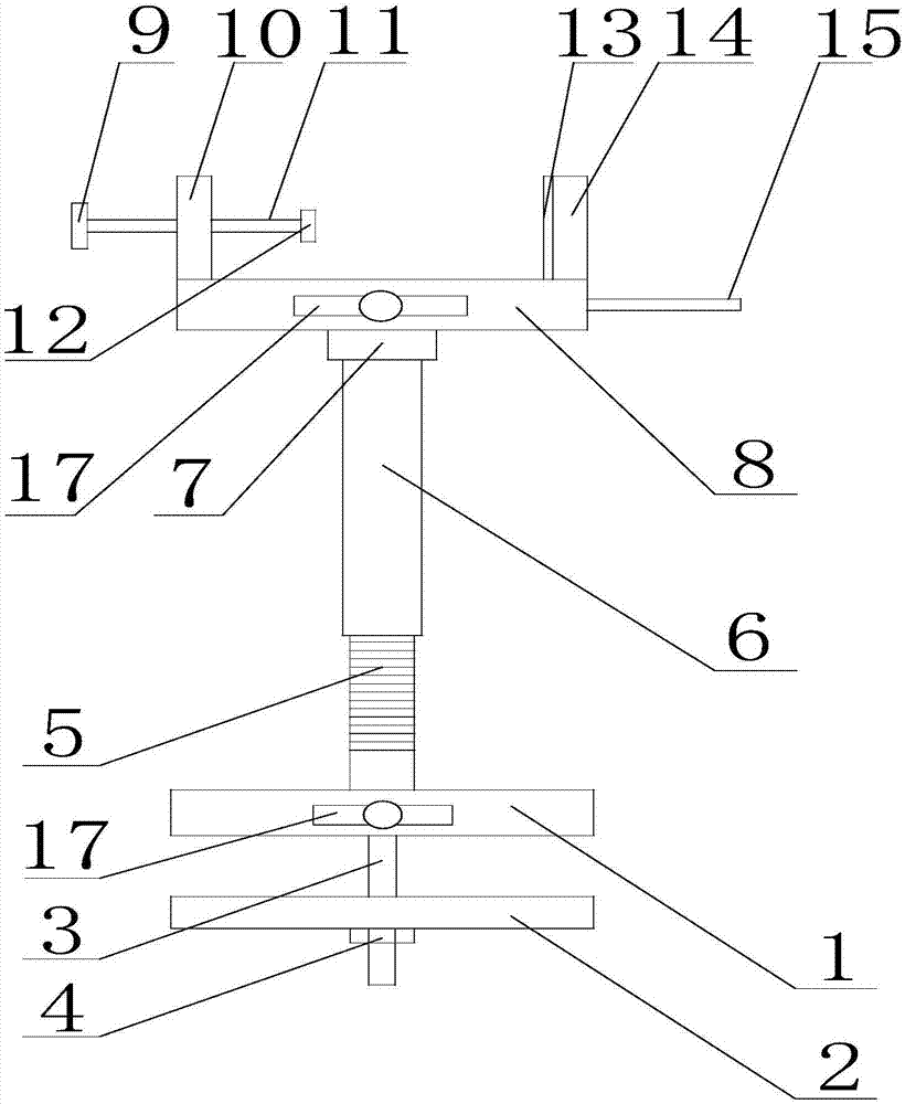
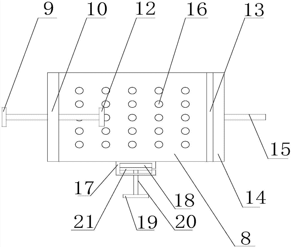
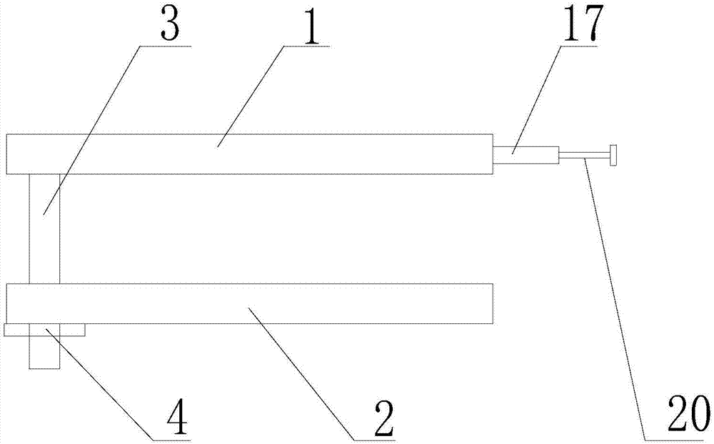
[0026] Such as Figure 1 to Figure 4 As shown, the remote video conferencing camera supporting device with fastening wiring function of the present invention includes a rectangular base 1, the bottom of the base 1 is provided with a connecting rod 3, the connecting rod 3 is located at the edge of the base 1, and the connecting rod 3 is provided with There are a clamping plate 2 and a nut 4, the clamping plate 2 and the nut 4 are both set on the connecting rod 3, and the connecting rod 3 is also inserted at the edge of the clamping plate 2, and the clamping plate 2 can be mounted on the connecting rod 3 Moving up and down, the connecting rod 3 and the nut 4 are threadedly connected, and the nut 4 is located under the clamping plate 2, the nut 4 can fix the clamping plate 2 on the connecting rod 3, and by rotating the nut 4, it can be adjusted The distance between the base 1 and the clamping plate 2 satisfies the clamping of conference tables of different thicknesses; the top of...


PUM


Abstract

The invention discloses remote video conference camera supporting equipment with a wire fastening function. The equipment comprises a base, a connecting rod is arranged on the base, and a clamping plate and a nut are arranged on the connecting rod. A supporting rod is arranged at the top of the base, a movable rod is arranged on the supporting rod, and a rotary component is arranged on the movable rod. A supporting table is arranged on the rotary component, and a first boss and a second boss are arranged at the top of the supporting table. A cross rod is arranged on the first boss, and the two ends of the cross rod are provided with a first adjusting handle and a first rubber pad correspondingly. A second rubber pad is arranged on the side wall of the second boss, and a second adjusting handle and vent holes are arranged on the base. Fixed blocks are arranged on the base and the side wall of the supporting table, and through holes, adjusting rods and openings are arranged on the fixed blocks. The adjusting rods are connected into the through holes, push plates are arranged on the adjusting rods, and the openings communicate with the through holes. The equipment can support a camera by being directly fixed to a conference table, and space is saved; and meanwhile, the wire can be prevented from falling off in the use process.

Description

technical field [0001] The invention relates to a camera auxiliary device, in particular to a remote video conference camera supporting device with the function of fastening wiring. Background technique [0002] With the progress of society and the development of information technology, video conferencing has gradually become the mainstream form of meeting. Video conferencing can realize multi-party audio and video interaction and is low in cost. Therefore, many enterprises and institutions have assembled their own video conferencing systems. At present, most of the camera fixtures used for video conferencing are tripod devices provided by manufacturers. Although the camera installation It is easy to move on the tripod device, but the tripod device takes up a certain space on the floor of the meeting room, especially for the meeting room where the space is not wide, it is easy to form obstacles to the normal activities of the people in the meeting room, and it is also easy ...

Claims


Application Information

Patent Timeline
Patent Type & Authority Applications(China)
IPC IPC(8): F16M13/02F16M11/08F16M11/18
CPCF16M13/022F16M11/08F16M11/18
Inventor 陈林瑶
Owner 盐城晟远致和信息技术咨询有限公司
Why Eureka
Try Eureka