
Light source combination method

A combination method and light source technology, applied in the direction of electrical components, electrical solid devices, circuits, etc., can solve problems such as incorrect

Active Publication Date: 2017-08-04
周卓辉
View PDF5 Cites 5 Cited by
  • Summary
  • Abstract
  • Description
  • Claims
  • Application Information

AI Technical Summary

Problems solved by technology

Therefore, it can be predicted that a light source to be tested with a high color rendering index (CRI) may not necessarily bring people good visual performance, situation, vitality, and power; It is not correct that the performance index indicates (or proves) the quality of the light source of the lighting equipment it sells

Method used


Image

  • Light source combination method
  • Light source combination method
  • Light source combination method

Examples


Embodiment Construction

[0065] In order to more clearly describe a combination method of a high-quality light source proposed by the present invention, preferred embodiments of the present invention will be described in detail below with reference to the drawings.

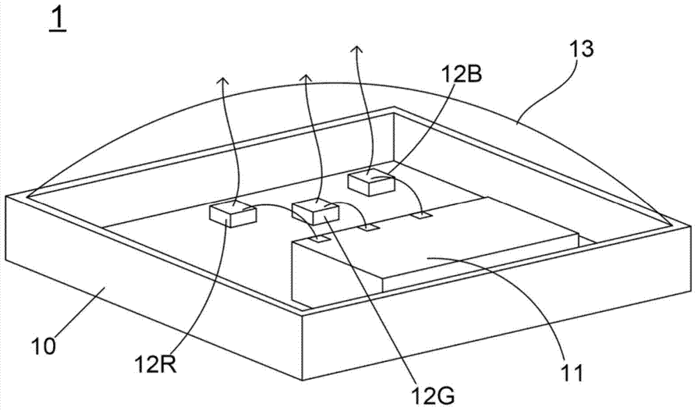
[0066] Before explaining the method of the present invention, first briefly introduce the structure of a light emitting unit (module). see image 3 , is a perspective view of a light emitting unit. like image 3 As shown, the light-emitting unit 1 includes: a housing body 10, a drive unit 11, a plurality of light-emitting elements, and a transparent cover 13; wherein, the plurality of light-emitting elements basically include a red light chip 12R, a yellow-green light Chip 12G and a Blu-ray chip 12B. Certainly, the present invention does not limit the light-emitting element to be a specific chip, so the light-emitting element may be an OLED chip, an AMOLED or an LED chip.

[0067] read on image 3 , and see also Figure 4A and Fig...


PUM


Abstract

Disclosed is a light source combination method. The light source combination method comprises the steps of (1) providing a plurality of light-emitting components, and driving the light-emitting components to give out multiple colored lights; (2) determining whether a Planck curve in a CIE coordinate graph is surrounded by multiple CIE coordinate positions corresponding to the multiple colored lights or not; if so, executing a step (3), and if not, executing the step (1) repeatedly; (3) mixing the multiple colored lights into one mixed light, wherein the mixed light has a specific CIE coordinate; (4) determining whether the specific CIE coordinate is positioned above the Planck curve in the CIE coordinate graph or not; if so, executing a step (6), and if not, executing a step (5); (5) driving the light-emitting components to adjust light intensity of one or more colored lights, and executing the step (3) repeatedly; and (6) performing further integration on the light-emitting components to form a light emitting unit or a light emitting module, wherein the light emitting unit or the light emitting module can give out a high-quality light source. By virtue of the method and the process, the light emitting unit which can give out the high-quality light source can be combined and manufactured by an engineer favorably.

Description

technical field [0001] The invention relates to the technical field of analyzing and defining the quality of light sources, especially a method for combining high-quality light sources. Background technique [0002] The use of light is an important application of human civilization, so the ancients could live by natural light, work at sunrise and rest at sunset. Since Edison invented the light bulb, with the advancement of science and technology, the light source used by humans has developed from light bulbs to incandescent bulbs (Incandescent bulbs) and fluorescent lamps (Fluorescent tubes); State Lighting (SSL) technology, such as light-emitting diode (Light-Emitting Diode, LED), organic light-emitting semiconductor (Organic Light-Emitting Diode, OLED) and polymer light-emitting diode (PolymerLight-Emitting Diode, PLED) are all solid-state lighting technologies ( SSL). [0003] Ergonomic Lighting Indicator (ELI) is a comprehensive lighting quality evaluation standard. s...

Claims


Application Information

Patent Timeline
Patent Type & Authority Applications(China)
IPC IPC(8): H01L25/075
Inventor 周卓辉何哲凯
Owner 周卓辉
Learn More