
injection molding machine

An injection molding machine, proportional technology, applied in the field of injection molding machines, can solve the problems of low precision of connecting rod and discontinuous temperature control of connecting rod, etc., and achieve the effect of improving precision and suppressing discontinuity

Active Publication Date: 2020-04-14
SUMITOMO HEAVY IND LTD
View PDF3 Cites 0 Cited by
  • Summary
  • Abstract
  • Description
  • Claims
  • Application Information

AI Technical Summary

Problems solved by technology

As a result, the temperature control of the connecting rod may become discontinuous, and the accuracy of the temperature control of the connecting rod may be lowered.

Method used


Image

  • injection molding machine
  • injection molding machine
  • injection molding machine

Examples


Embodiment Construction

[0022] Hereinafter, the embodiments of the present invention will be described with reference to the drawings. In each of the drawings, the same or corresponding components are given the same or corresponding symbols and their descriptions are omitted.

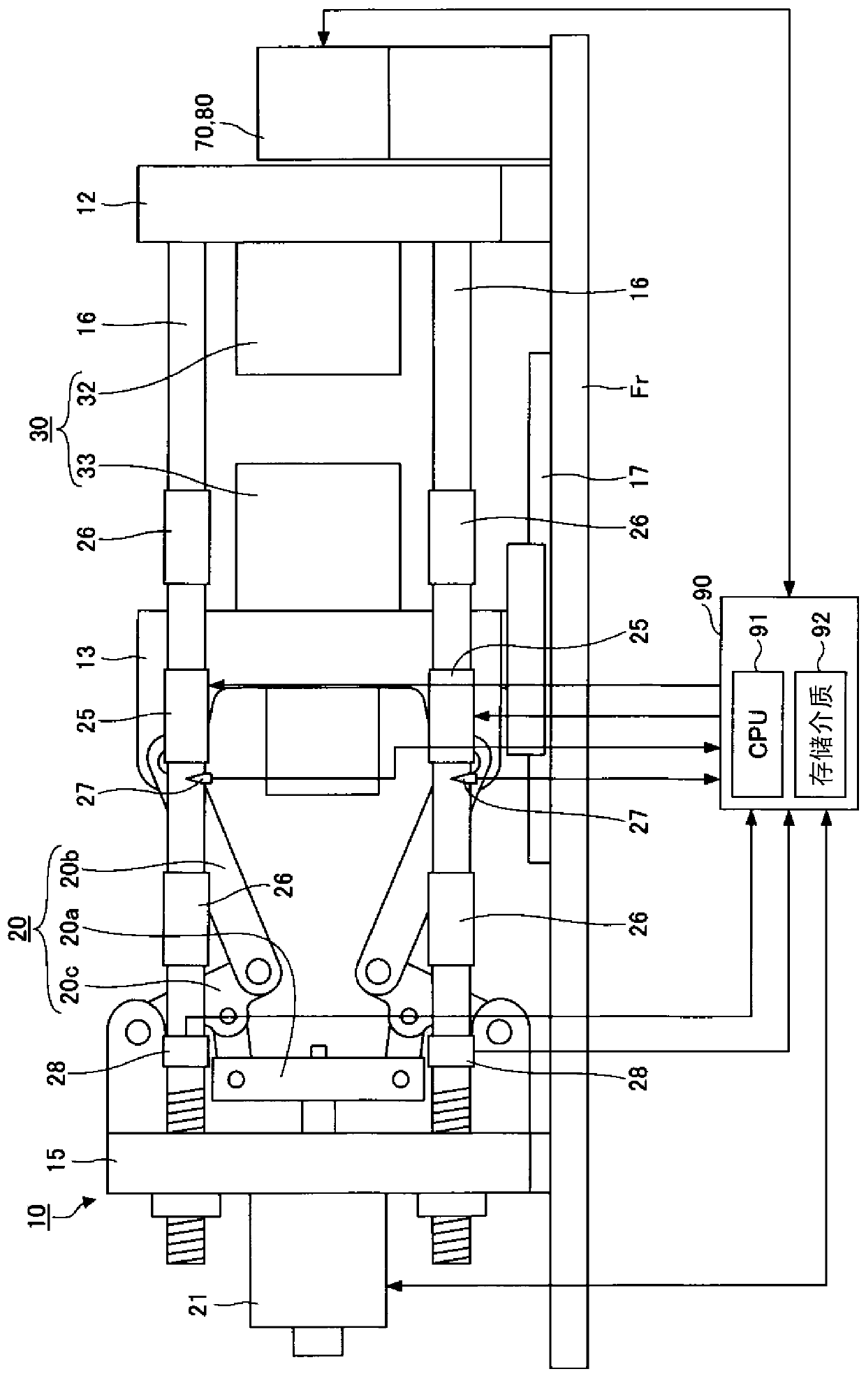
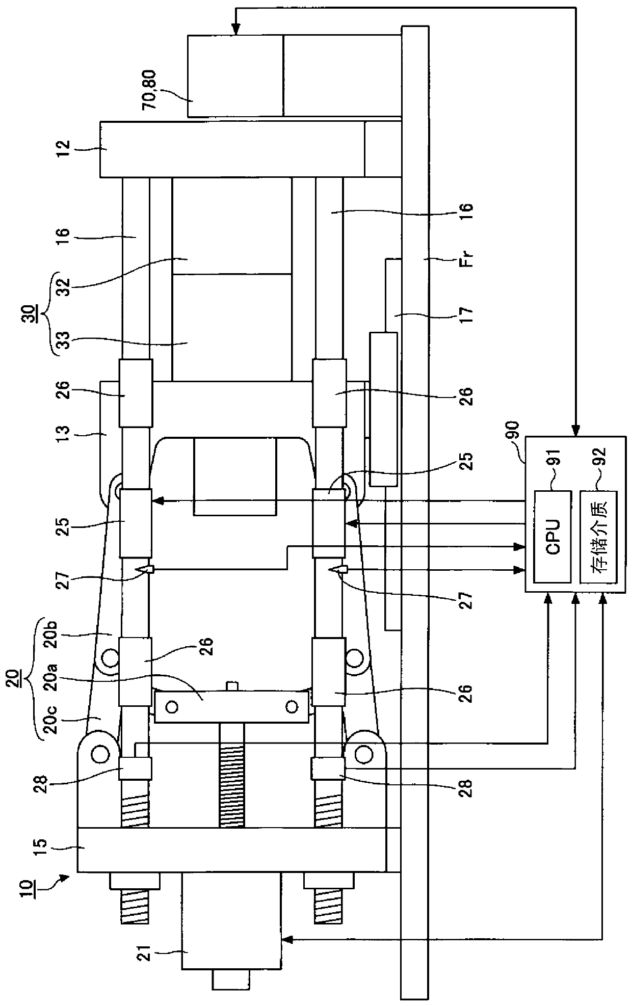
[0023] figure 1 It is a figure which shows the state at the time of completion of mold opening of an injection molding machine based on an embodiment. figure 2 It is a figure which shows the state at the time of mold clamping of the injection molding machine based on an embodiment. The injection molding machine has a frame Fr, a mold clamping device 10, an operating device 70, a display device 80, a controller 90, and the like.

[0024] The controller 90 has a CPU (Central Processing Unit) 91 and a storage medium 92 such as a memory. The controller 90 causes the CPU 91 to execute a program stored in the storage medium 92, thereby controlling the mold clamping device 10, the operating device 70, the display device 80, and the like....


PUM


Abstract

The present invention provides an injection molding machine capable of suppressing the discontinuity of the temperature control of the connecting rod and improving the accuracy of the temperature control of the connecting rod. The injection molding machine of the present invention includes: a plurality of connecting rods extending according to mold clamping force; a heater for heating the connecting rods; and a controller for controlling the heaters, the controller for adjusting the heaters The temperature of the heating portion of the connecting rods is heated, thereby adjusting the balance of the axial force of the plurality of connecting rods, and the reference temperature of the heating portion for adjusting the balance is set to be higher than that based on the The stable temperature of the said heating part at the time of non-heating of a heater is high temperature.

Description

Technical field [0001] This application claims priority based on Japanese Patent Application No. 2016-016663 filed in Japan on January 29, 2016. The entire content of its application is used in this specification by reference. [0002] The invention relates to an injection molding machine. Background technique [0003] The injection molding machine has a mold clamping device that performs mold closing, mold clamping, and mold opening of the mold device. The mold clamping device has a plurality of links extending in accordance with the mold clamping force (for example, refer to Patent Document 1). The clamping force is dispersed and applied to a plurality of links, so that each link extends. The force that hinders the extension of the connecting rod is called the axial force. [0004] When there is a difference in the effective length of multiple connecting rods, a difference in axial force is generated between the connecting rod with a shorter effective length and the connecting ...

Claims


Application Information

Patent Timeline
Patent Type & Authority Patents(China)
IPC IPC(8): B29C45/78B29C45/76B29C45/66B29C33/22
CPCB29C33/22B29C45/66B29C45/7653B29C45/78B29C2945/7604B29C2945/76531
Inventor 森田洋森谷知宽
Owner SUMITOMO HEAVY IND LTD
Learn More