Temperature sensor

a technology of temperature sensor and sensor body, which is applied in the direction of heat measurement, material thermal conductivity, instruments, etc., can solve the problems of unsolved failure, heavy damage, and injuring people, and achieve the effect of reducing the cost of failure, and improving the quality of failur

Active Publication Date: 2019-08-13
EMPHASE SRL
View PDF5 Cites 0 Cited by
  • Summary
  • Abstract
  • Description
  • Claims
  • Application Information

AI Technical Summary

Benefits of technology

[0016]the method comprise the step of filtering the path length of the maximum of intensity for suppressing discontinuity of the trajectory induced by vibrations;

Problems solved by technology

Failure scenarios like thermal runaway due to soil drying, junction failures, leaks or external mechanical actions can cause heavy damages and injure people.
Any unsolved failure can also become very expensive.
Conventional fibre optic temperature monitoring is an efficient tool to tackle those issues but is reserved for strategic infrastructure because of the high cost of the existing solutions (based on Raman and Brillouin scatterings).
Temperature sensing based on pattern recognition is rather tricky for three main reasons.
The temperature is therefore obtained by an integration operation (versus time), which causes error drifts.
Secondly discrimination between a heating phase (positive temperature variation) and a cooling phase (negative temperature variation) is not straightforward.

Method used


Image

  • Temperature sensor
  • Temperature sensor
  • Temperature sensor

Examples


Embodiment Construction

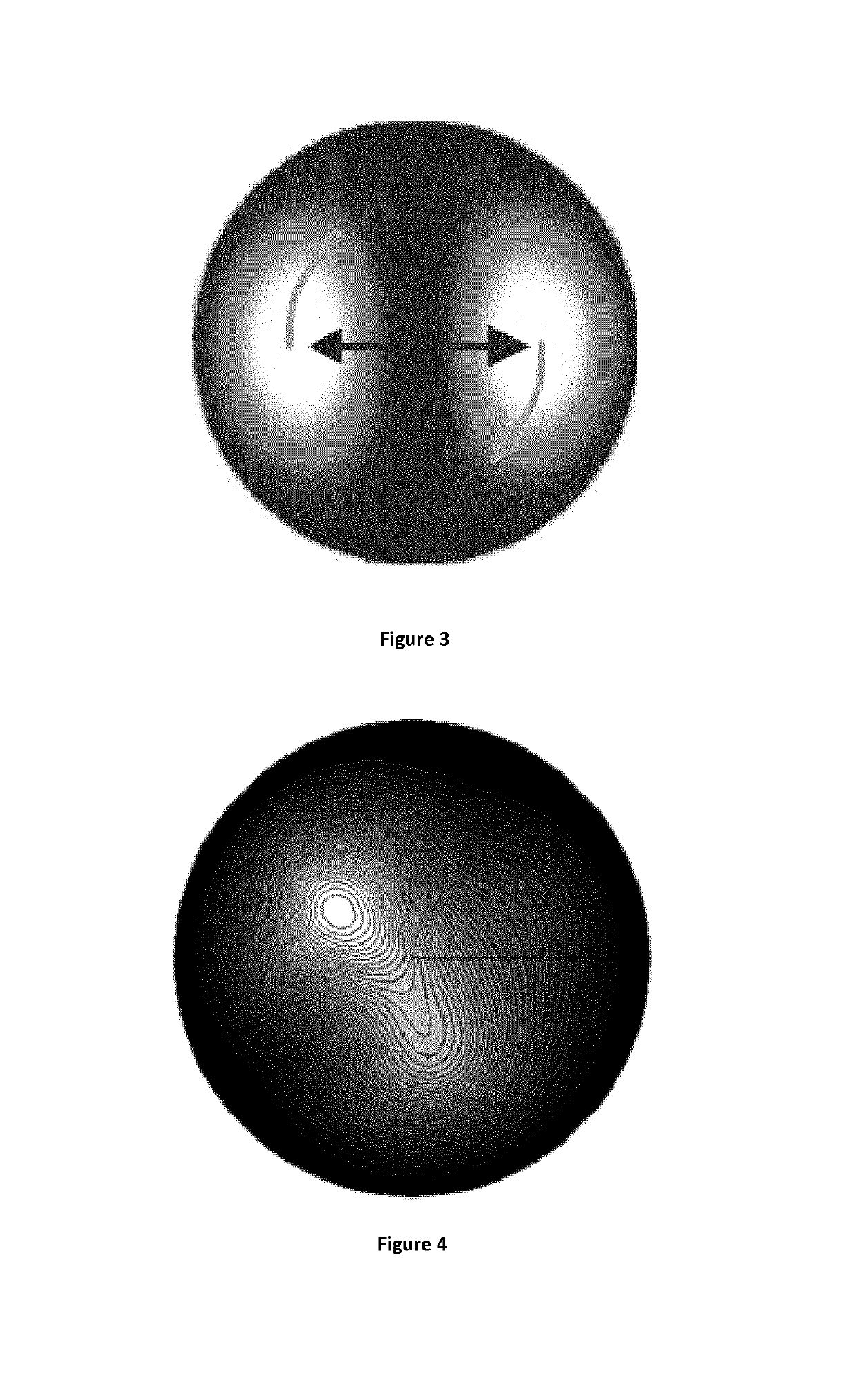
[0051]In the present invention a few mode optical fibre is an optical fibre operated at a wavelength at which more than one propagation mode is allowed, but wherein the number of propagation mode is limited to a value permitting an interference pattern with one or transiently two lobes.

This few modes conditions can be obtained in so called few-modes fibres. Typically, this is obtained by using an optical fibre having less than 30 (preferably less than 12) propagation modes at the used wavelength.

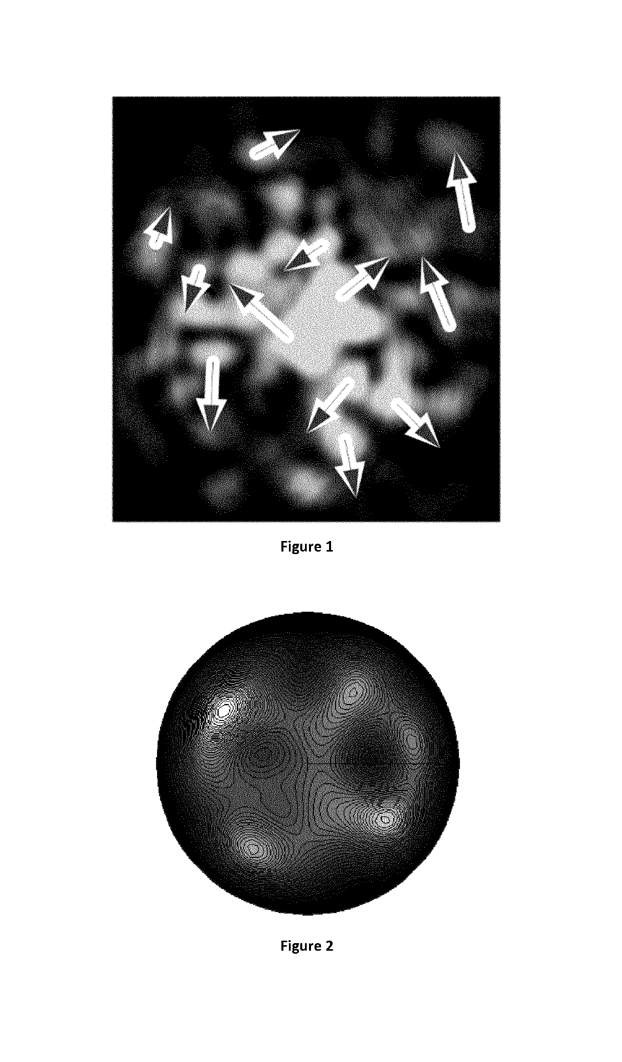
[0052]In the present description, the term “lobe” is to be understood as as a contiguous part of the interference pattern whose intensity is larger than a threshold level and which comprises a local maximum of intensity . . .

[0053]Preferably, the number of propagation mode is limited to a value permitting only one lobe. Nevertheless, a second lobe can appear transiently.

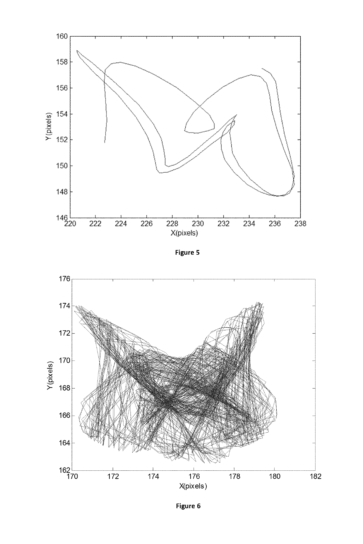
[0054]Temperature affects the light propagation in an optical fibre mainly in two ways: thermal expansion and refractive in...


PUM

PropertyMeasurementUnit
temperatureaaaaaaaaaa

Abstract

The present invention is related to a method for determining distributed temperature variation of a few mode optical fiber comprising the steps of:—providing a few mode optical fiber;—enlighting a first end of said few mode optical fiber by means of a coherent light source;—determining the interference pattern of coherent light at a second end of the optical fiber;—selecting one maximum of intensity at the second end of the optical fiber by spatially filtering the enlighting at the first end of the optical fiber;—determining the path length of the trajectory of the selected maximum of intensity;—based upon the determined path length of the trajectory of the selected maximum of intensity, determining the temperature variation of the few mode optical fiber.

Description

FIELD OF THE INVENTION[0001]The present invention is related to a method for determining distributed temperature of an optical fibre.[0002]Another aspect of the invention is related to a temperature sensor implementing the method of the invention.BACKGROUND[0003]Thermal monitoring integrated along underground power cables is of high interest for electricity, gas and liquid transport infrastructure management. Failure scenarios like thermal runaway due to soil drying, junction failures, leaks or external mechanical actions can cause heavy damages and injure people. Any unsolved failure can also become very expensive. Moreover, lifetime estimation is of great interest to optimize asset management and forecast investments. Conventional fibre optic temperature monitoring is an efficient tool to tackle those issues but is reserved for strategic infrastructure because of the high cost of the existing solutions (based on Raman and Brillouin scatterings). The scope of application of the inv...

Claims


Application Information

Patent Timeline
Patent Type & Authority Patents(United States)
IPC IPC(8): G01N25/18G01K11/32
CPCG01K11/32
Inventor MUSIN, FRÉDÉRICWUILPART, MARCMEGRET, PATRICE
Owner EMPHASE SRL
Why Eureka
Try Eureka