Intelligent warning device and working method thereof
A working method and equipment technology, applied in signal transmission systems, instruments, portable emergency signal devices, etc., can solve problems such as hidden safety hazards and time-consuming problems, and achieve the effect of eliminating hidden safety hazards and saving users' time
- Summary
- Abstract
- Description
- Claims
- Application Information
AI Technical Summary
Problems solved by technology
Method used
Image

Examples
Embodiment 1
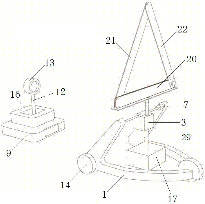
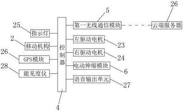
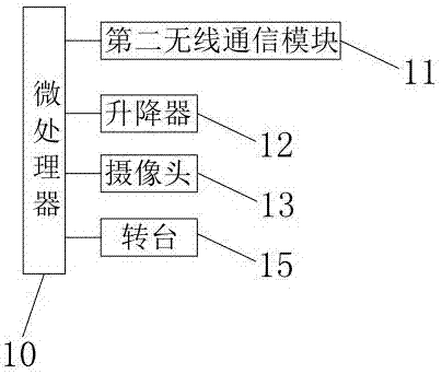
[0034] Embodiment 1: a kind of intelligent warning device of this embodiment, such as figure 1 , figure 2 , image 3As shown, it includes a warning trolley and a positioning device. The warning trolley includes a trolley support 1, a moving mechanism 2 is provided at the bottom of the trolley support 1, a control box 3 is provided on the trolley support 1, a controller 4 is provided on the control box 3, a first wireless The communication module 5, the electric telescopic module 6 and the GPS module 26, the top of the upper telescopic rod 7 of the electric telescopic module 6 is provided with a triangle warning sign 8, the bottom of the lower telescopic rod 29 of the electric telescopic module 6 is provided with a counterweight 17, and the controller 4 Respectively electrically connected with the mobile mechanism 2, the first wireless communication module 5, the electric telescopic module 6 and the GPS module 26, the positioning device includes a base 9, the base 9 is provid...
Embodiment 2
[0055] Embodiment 2: a kind of intelligent warning device of this embodiment, such as image 3 , Figure 5 , Figure 6 As shown, it includes a warning trolley and a positioning device. The warning trolley includes a trolley support 1, a moving mechanism 2 is provided at the bottom of the trolley support 1, a control box 3 is provided on the trolley support 1, a controller 4 is provided on the control box 3, a first wireless Communication module 5, electric telescopic module 6, GPS module 26 and air pump 18, the upper telescopic rod 7 top of electric telescopic module 6 is provided with triangular warning sign 8, and the lower telescopic rod 29 bottom of electric telescopic module 6 is provided with vacuum sucker 19, vacuum The sucker 19 is connected with the air pump 18 through the connecting pipe, and the controller 4 is electrically connected with the mobile mechanism 2, the first wireless communication module 5, the electric telescopic module 6, the GPS module 26 and the a...
PUM
 Abstract
Description
Claims
Application Information
 - Generate Ideas
- Intellectual Property
- Life Sciences
- Materials
- Tech Scout
- Unparalleled Data Quality
- Higher Quality Content
- 60% Fewer Hallucinations
Browse by: Latest US Patents, China's latest patents, Technical Efficacy Thesaurus, Application Domain, Technology Topic, Popular Technical Reports.
© 2025 PatSnap. All rights reserved.Legal|Privacy policy|Modern Slavery Act Transparency Statement|Sitemap|About US| Contact US: help@patsnap.com