A device and method for in-situ shear strength testing of rocks

A technology of shear strength and measuring device, which is applied in the direction of applying stable shear force to test the strength of materials, etc. It can solve problems such as the regulation of the normal force application range, the damage of the test object, and the complexity of the preparation process, so as to avoid shear stress Larger test results, avoid stress instability, and strong environmental adaptability

Active Publication Date: 2019-06-04
CHINA UNIV OF MINING & TECH
View PDF8 Cites 0 Cited by
  • Summary
  • Abstract
  • Description
  • Claims
  • Application Information

AI Technical Summary

Problems solved by technology

[0004] ① The size of the test object is large, and it is necessary to manually dig and chisel out the cubic sample to be tested before the on-site test, and the preparation process is complicated;
[0005] ②Although the test object is the on-site rock mass, it has been isolated from the surrounding rock mass after manual excavation and chiseling, and has lost its in-situ stress state, and due to the unloading effect, a large amount of damage will occur inside the test object, resulting in the strength test of the test object. Inaccurate;
[0006] ③The test period is long and the price is expensive. Since the in-situ direct shear test uses instruments including jacks, hydraulic cylinders, rigid pillars, displacement gauges, etc. on the spot, and some positions do not meet the reaction force conditions, additional loads must be prepared. Therefore, this method is prepared The process is complex, involving many and scattered instruments, many personnel, long time and high cost
[0008] ① The device and method apply the shear force and normal force to one indenter. During the test, the normal force is applied to press the 1mm-high convex part of the indenter into the rock and continue to apply the normal force until the design value, and then apply a shear force by tensioning the jack connected to the shear head pull rod outside the borehole, the pressure head moves out of the borehole, and the protrusion on the pressure head shears the rock to complete the shearing, and at this time The rock adjacent to the sheared rock in the direction outside the borehole (that is, the shear direction) will produce a blocking effect at this time, resulting in a larger shear force test result;
[0009] ②The bulge on the indenter of the device and method that exerts the shear force is only 1 mm high. If the rock on the wall of the drill hole is broken or deformed, it cannot be effectively inserted into the rock, which will easily lead to inaccurate test results;
[0010] ③The device and method are based on the Mohr-Coulomb criterion, that is, the relationship between the shear strength and the normal force is linear, but the range of application of the normal force is not specified when the device and method are tested
If the actual applied normal force is too high, the relationship between normal force and shear stress will be nonlinear, which will lead to errors in the cohesion and internal friction angle obtained by the test;
[0011] ④The device and method monitor the normal force and shear force of the pressure instrument is mechanical, the minimum resolution is 0.5MPa, in addition, the normal force and shear force are manually applied through the hand oil pump during the test, two aspects lead to manual readings large time error;
[0012] ⑤The device and method can only test the shear stress, not the shear displacement, so the shear stress-shear strain curve cannot be obtained

Method used


Image

  • A device and method for in-situ shear strength testing of rocks
  • A device and method for in-situ shear strength testing of rocks
  • A device and method for in-situ shear strength testing of rocks

Examples


Embodiment Construction

[0048] An embodiment of the present invention will be further described below in conjunction with accompanying drawing:

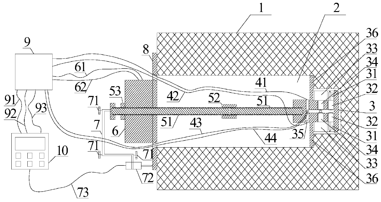
[0049] like figure 1 As shown, the rock in-situ shear strength measurement device includes a shear probe 3 arranged at the bottom of a stepped borehole 2 on the rock 1 to be tested, and the shear probe 3 is provided with a normal force and a shear force loading device, the normal force and shear force loading device includes a plurality of radially arranged oil cylinders arranged in the shear probe 3, and the oil cylinders include a symmetrically arranged shear stress loading plate oil cylinder 32 and a normal force loading plate oil cylinder 34. The shear stress loading plate oil cylinder 32 and the normal force loading plate oil cylinder 34 are connected with a shear probe oil circuit 35, the shear stress loading plate oil cylinder 32 is provided with a shear stress loading plate 31, and the normal force loading plate oil cylinder 34 is provided with a T...


PUM


Abstract

The invention discloses a rock field shear strength test device and method, and which are suitable to be used in the field of rock detection. The rock field shear strength test device comprises a shear test head, wherein a shear stress loading pull rod is arranged at a tail end of the shear test head; the shear test head is connected with a servo oil pump which is arranged outside a step-shaped borehole through an oil circuit; a borehole orifice baffle plate, a shear stress loading jack and a shear stress loading jack locking nut are arranged at a tail end of the shear stress loading pull rod in sequence; the shear stress loading jack and the borehole orifice baffle plate are extruded and fixed on a rock at a borehole orifice; a shear displacement test device is arranged between the tail end of the shear stress loading pull rod and the borehole orifice baffle plate; the servo moil pump and the shear displacement test device are connected with a stress-displacement data collection and display system through circuits. Shear force is applied to the borehole by the shear test head, and the cohesive strength and the internal friction angle of a tested object are obtained by regression fitting according to a Mohr-coulomb yielding criterion. The rock field shear strength test device has a simple structure, is accurate in tests, and can be used for monitoring a displacement value all the time in a pulling process.

Description

technical field [0001] The invention relates to a strength measuring device and method, and is especially suitable for the in-situ shear strength measuring device and method of rock used in the study of rock shear strength. Background technique [0002] The in-situ shear strength of rock is an important basic parameter for geotechnical engineering design. The in-situ shear strength test of rock is a necessary prerequisite for the stability assessment of engineering rock mass and the realization of geotechnical engineering excavation and support design. [0003] At present, the in-situ shear strength test method of rock is mainly the in-situ shear test method, and the in-situ shear test method mainly has the following disadvantages: [0004] ① The size of the test object is large, and it is necessary to manually dig and chisel out the cubic sample to be tested before the on-site test, and the preparation process is complicated; [0005] ②Although the test object is the on-s...

Claims


Application Information

Patent Timeline
Patent Type & Authority Patents(China)
IPC IPC(8): G01N3/24
CPCG01N3/24
Inventor 孟波靖洪文杨圣奇王迎超蔚立元齐燕军
Owner CHINA UNIV OF MINING & TECH
Why Eureka
Try Eureka