Charged-particle microscope with astigmatism compensation and energy-selection
A charged particle microscope, charged particle technology, applied in the field of corrected beams, can solve problems such as harmful effects, achieve extended use, reduce cost and complexity, and improve uptime
- Summary
- Abstract
- Description
- Claims
- Application Information
AI Technical Summary
Problems solved by technology
Method used
Image

Examples
Embodiment 1
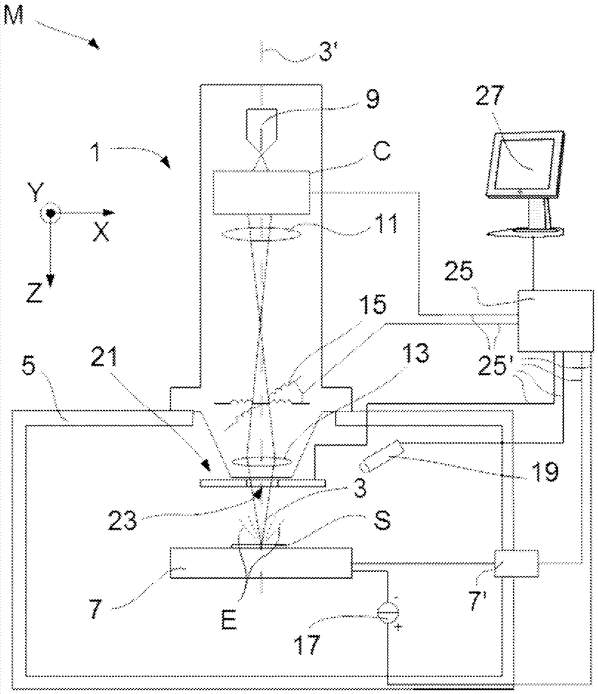
[0078] figure 1 is a highly schematic depiction of an embodiment of a CPM in which the invention is implemented; more specifically, it shows an embodiment of a microscope M, which in this case is a SEM (although in the context of the present invention, its Could for example be (S)TEM, or ion-based microscopy, just right). Microscope M comprises an illuminator (particle-optical column) 1 which generates a beam 3 of input charged particles (in this case an electron beam) propagating along a particle-optical axis 3'. The illuminator 1 is mounted on a vacuum chamber 5 comprising a sample holder 7 and associated stage / actuator 7' for holding / positioning the sample S. The vacuum chamber 5 is evacuated using a vacuum pump (not depicted). With the help of a voltage source 17, the sample holder 7, or at least the sample S, can be biased (floated) to a potential relative to ground, if desired.
[0079] The illuminator 1 (in the present case) comprises an electron source 9 (such as, ...
Embodiment 2
[0091] Example 2
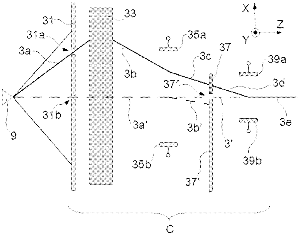
[0092] figure 2 schematically illustrates an embodiment of a method / corrector device according to the invention (see also figure 1 ) structure and operation. exist figure 2 In , the source 9 emits charged particles (such as electrons) in multiple directions, which are depicted here by the cones emanating from the tip of the source 9 . The spatial filter 31 (extractor aperture plate) comprises off-axis apertures 31a and on-axis apertures 31b considered relative to the optical axis 3'. The input beam 3a propagating from the source 9 through the aperture 31a passes eccentrically through the astigmatism corrector (quadrupole lens) 33 (centred on the axis 3') and emerges from the astigmatism corrector 33 as an intermediate beam 3b; On the other hand, the (axial) beam 3 a ′ passes non-eccentrically through the center of the astigmatism corrector 33 . As already explained above, the intermediate beam 3b will demonstrate (double) astigmatism and energy dis...
Embodiment 3
[0103] The following is an example of a direct astigmatism corrector adjustment (calibration) routine that can be used in the present invention:
[0104] (i) For the first of the line focuses (e.g. the distal line focus, furthest from the astigmatism corrector), one chooses a specific differential excitation of the astigmatism corrector (E D ) and adjust the non-differential excitation of the astigmatism corrector (E C ) for optimal focus at the slit plane. People then target E D Repeat the process for at least one other value of , allowing to make E C Contrast E D The first graph line of .
[0105] (ii) repeating the process in (i) for the second of the line focuses (proximal line focus, closest to the astigmatism corrector), resulting in E C Contrast E D the second graph line of .
[0106] (iii) E at the intersection of the first and second graph lines D The value of is the value that will minimize the axial separation of the first and second line focuses.
[0107] ...
PUM
 Abstract
Description
Claims
Application Information
 - R&D Engineer
- R&D Manager
- IP Professional
- Industry Leading Data Capabilities
- Powerful AI technology
- Patent DNA Extraction
Browse by: Latest US Patents, China's latest patents, Technical Efficacy Thesaurus, Application Domain, Technology Topic.
© 2024 PatSnap. All rights reserved.Legal|Privacy policy|Modern Slavery Act Transparency Statement|Sitemap