
Automatic wall slotting device

An automatic, wall technology, applied in the direction of stone processing tools, work accessories, manufacturing tools, etc., can solve the problems of waste of labor, physical injury, dust and other problems, to reduce manual labor and improve cutting efficiency.

Active Publication Date: 2017-08-11
SHANXI INSTALLATION GRP CO LTD
View PDF6 Cites 8 Cited by
  • Summary
  • Abstract
  • Description
  • Claims
  • Application Information

AI Technical Summary

Problems solved by technology

[0003] Now the wiring grooves in the wall are often cut by construction workers with toothless saws, and then smashed with electric picks, which requires continuous labor of construction equipment and workers. In addition, electric picks and toothless saws consume a lot of physical strength, which is a waste of time. While a large number of workers are working, the cutting produces a lot of dust, which is very harmful to the workers

Method used


Image

  • Automatic wall slotting device
  • Automatic wall slotting device
  • Automatic wall slotting device

Examples


Embodiment Construction

[0019] The present invention is realized through the following technical solutions:

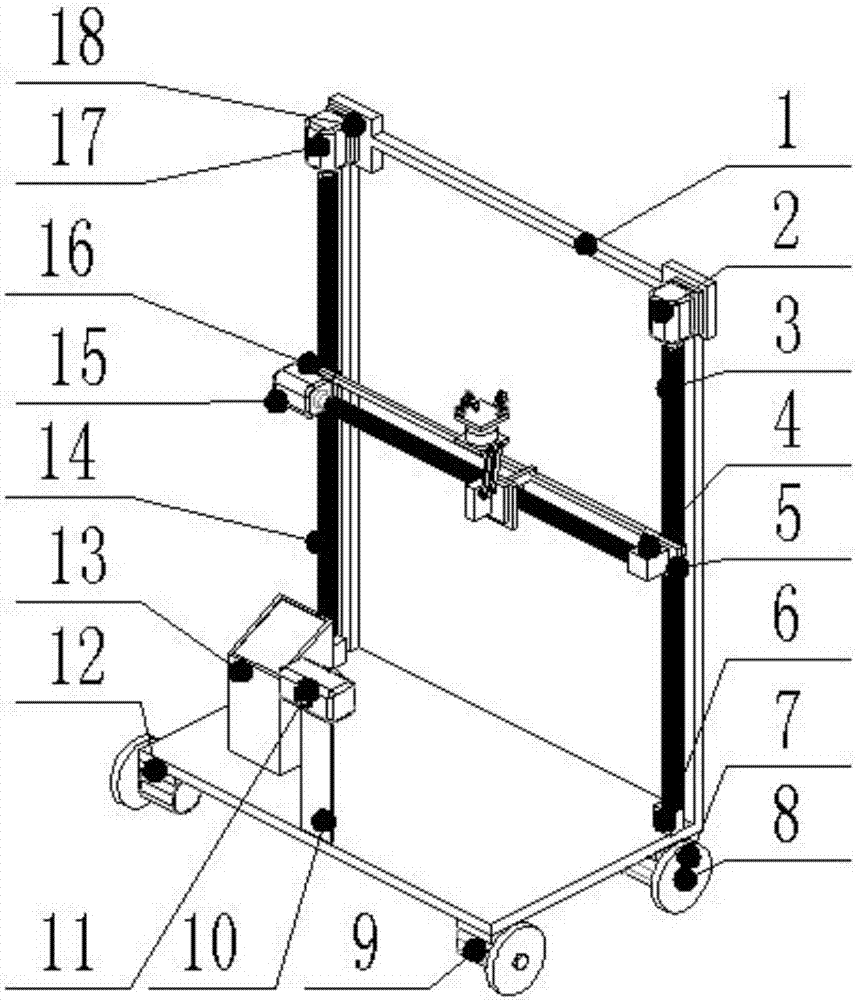
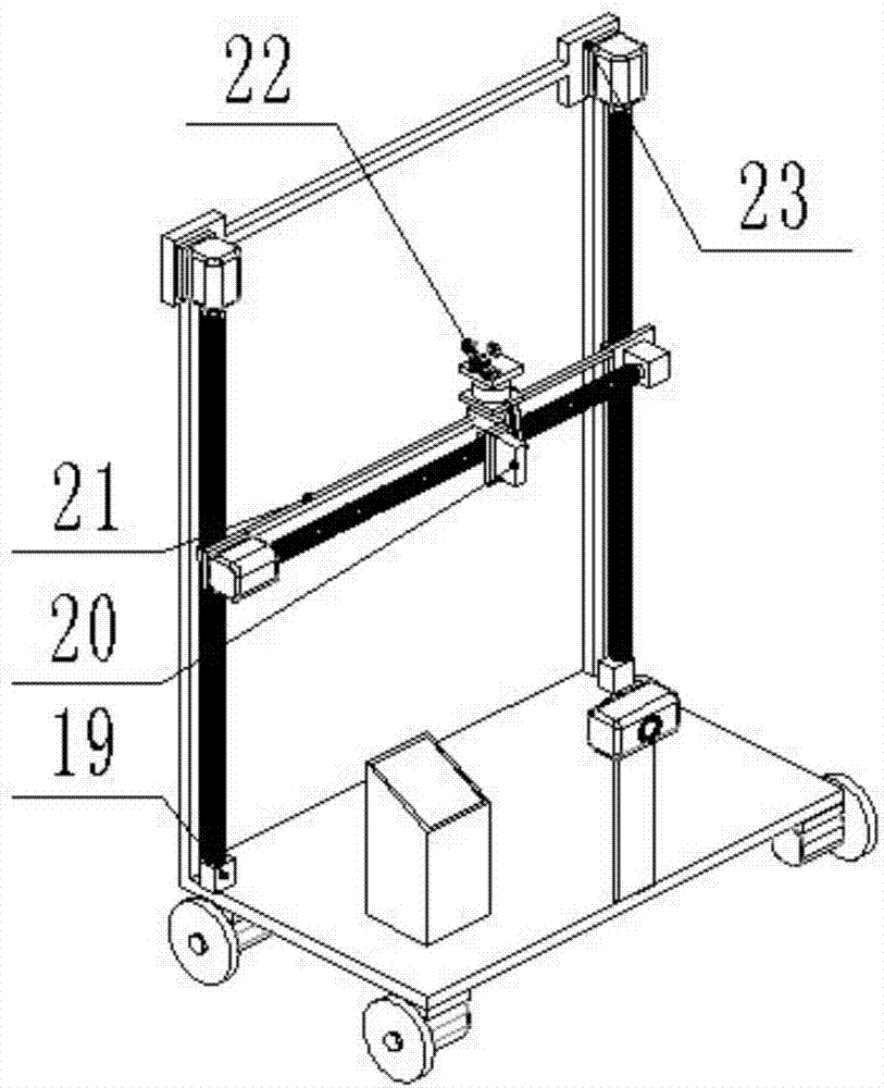
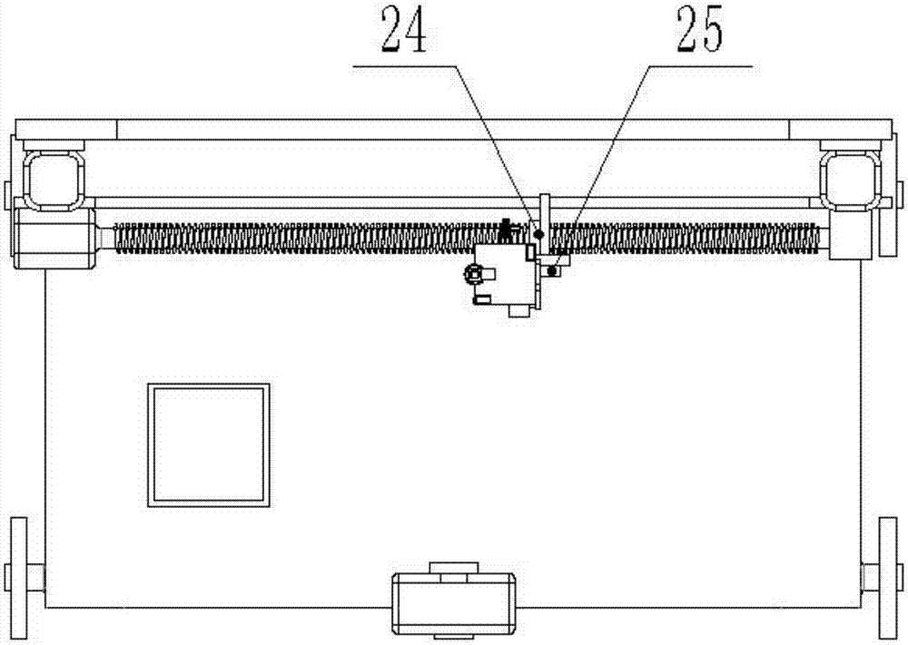
[0020] An automatic wall slotting device, comprising a first bracket 1, a first motor 2, a first screw 3, a second screw base 4, a first screw nut 5, a first screw base 6, and wheels 7 , wheel spindle 8, second motor 9, camera base 10, camera 11, second motor base 12, controller 13, third lead screw 14, third motor 15, third lead screw nut 16, fourth motor 17. The fourth motor base 18, the third screw base 19, the steering gear 20, the feed rod 21, the cutting device 22, the first motor base 23, the second screw nut 24, the steering gear base 25, the first Two supports 26, the third support 27 and the second lead screw 28, the first support 1 is fixed with the second motor base 12, the first motor 2 is installed on the first motor base 23, the first motor base 23, the first A screw 3 is fixed on the first motor 2 and installed concentrically with the first motor 2, the second screw base 4 is...


PUM


Abstract

The invention discloses an automatic wall slotting device, and belongs to the field of building construction equipment. A first support and a second motor base are fixed. A first lead screw is fixed to a first motor. A second lead screw base is arranged on a first lead screw nut. A camera base is arranged at the lower portion of the first support. The second motor base and the first support are fixed. A third lead screw is arranged on a fourth motor spindle. A third motor is arranged on a third lead screw nut. A fourth motor base is fixed to the upper left portion of the first support. A cutting device is arranged on a second support. A steering engine base is arranged on a second lead screw nut, and a second lead screw and a third motor are fixed. According to the automatic wall slotting device, the horizontal movement is driven through rotation of the lead screws, concrete at the slotting position is cut and removed through the cutting device, the manual labor is reduced, and efficiency is improved.

Description

technical field [0001] The invention relates to an automatic wall slotting device. Specifically, the rotation of the lead screw drives the horizontal movement, and the cutting device realizes the cutting and clearing of the concrete at the slotting position, which belongs to the field of building construction equipment. Background technique [0002] With the development of urban construction in our country, the urban population is increasing and building construction is also increasing. In building construction, there are more and more wiring grooves on the wall. The opening of wiring grooves is not only arranged on ordinary walls. It is also possible to open the load-bearing wall, which has higher and higher requirements for the slotting work. Not only the area of ​​the wall to be processed is large, but also the technical difficulty is high. [0003] Now the wiring grooves in the wall are often cut by construction workers with toothless saws, and then smashed with electric...

Claims


Application Information

Patent Timeline
Patent Type & Authority Applications(China)
IPC IPC(8): B28D1/18B28D7/00
CPCB28D1/18B28D7/00
Inventor 赵子宁钟建筑
Owner SHANXI INSTALLATION GRP CO LTD
Learn More