
Safety devices for increased safety when using battery systems

A technology of safety devices and battery devices, which is applied in the direction of batteries, secondary batteries, battery pack components, etc., to achieve the effect of avoiding aging and avoiding failure

Active Publication Date: 2021-03-30
ROBERT BOSCH GMBH
View PDF7 Cites 0 Cited by
  • Summary
  • Abstract
  • Description
  • Claims
  • Application Information

AI Technical Summary

Problems solved by technology

In this case, defective battery packs can be bridged electrically by means of a current bypass

Method used


Image

  • Safety devices for increased safety when using battery systems
  • Safety devices for increased safety when using battery systems
  • Safety devices for increased safety when using battery systems

Examples


Embodiment Construction

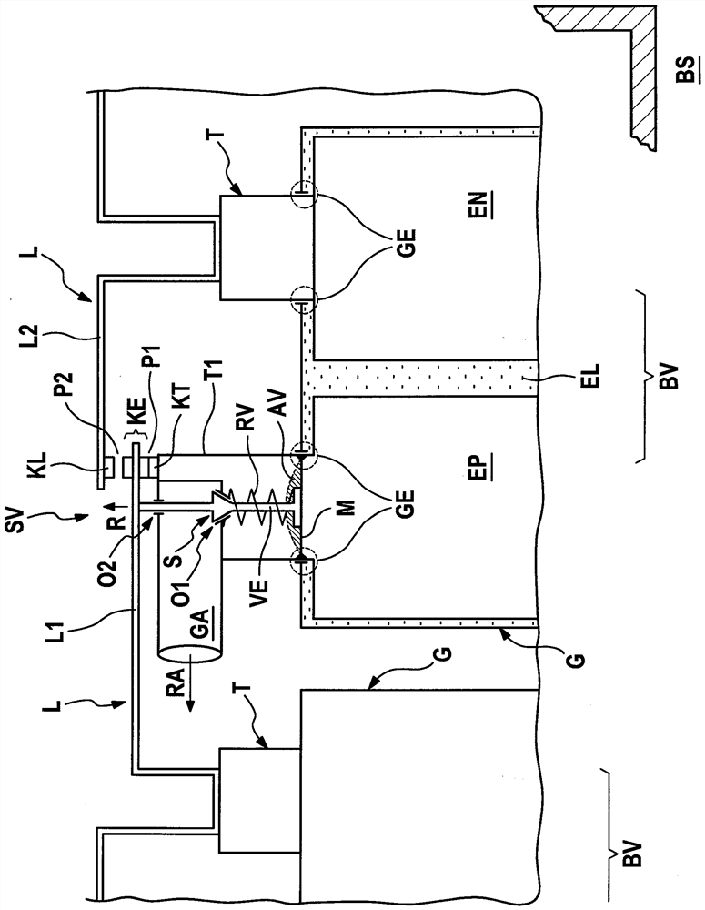
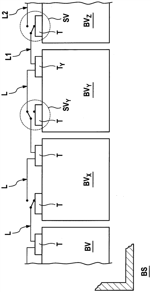
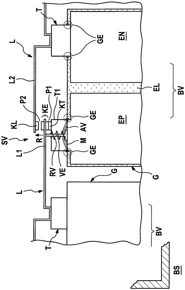
[0029] exist figure 1 A safety device according to the invention for increasing safety when using a battery system according to a first embodiment is schematically shown in FIG. Safety devices are denoted by SV. The battery system is denoted by BS. The battery system BS comprises a plurality of battery arrangements BV electrically connected in series. T is used to designate a terminal, wherein terminal T is suitable for electrical contacting of one battery arrangement BV with the other battery arrangement BV. Use GE to designate the gas-tight electrode guide, which is arranged at the housing G of the battery device BV and which prevents: substances, especially gases, from being trapped at the point where the terminals T sticks out through the shell G) moves out.

[0030] The battery arrangement BV has a positive electrode EP, a negative electrode EN and an electrolyte EL, all of which are arranged in a housing G of the battery arrangement BV.

[0031]The safety device SV ...


PUM


Abstract

The present invention is based on the use of a battery system (BS), especially the lithium ion battery system, which improves the safety device (SV).Among them, the safety device (BV) is applicable to the electrical crossing of at least one battery device (BV). Among them, the safety device (SV) has contact components (KE), and the contact element can occupy the first position (P1) and the second position (P2), where the contact element (KE) is located in the first position (P1), at least one battery device (BV) is connected in series, and when) When in the second position (P2), at least one battery device (BV) was called by electricity. Among them, the safety device (SV) had a callback device (RV) in orderThe status parameter of at least one battery device (BV) is moved from the second position (P2) to the first position (P1).

Description

technical field [0001] According to the invention, the invention concerns a safety device for increasing the safety when using a battery system, a battery system and a use of the battery system. Background technique [0002] Safety devices for increasing the safety when using battery systems are known from the prior art. Thus, for example, DE 10 2007 017 018 A1 shows a battery with a plurality of cells, wherein, in the event of an overvoltage built up in one of the cells, a battery is disclosed for the electrical bridging of the cells Battery jumper device. The battery jumper device comprises a movable, controllable electrical contact element which can be switched from a first switching state into a second switching state. [0003] Furthermore, DE 10 2012 222 836 A1 discloses housings for gas-tight accumulators, wherein, within the framework of one embodiment, the housing according to the invention has a proportional valve which depends on the pressure in the interior of t...

Claims


Application Information

Patent Timeline
Patent Type & Authority Patents(China)
IPC IPC(8): H01M10/42H01M50/51
CPCH01M10/42H01M10/4207H01M2220/20H01M50/51H01M10/0525H01M2200/20Y02E60/10H01M50/3425H01M50/578
Inventor J.魏克曼T-E.博赫达
Owner ROBERT BOSCH GMBH
Learn More