
Double-reflecting plate of base station antenna

A technology of base station antenna and reflector, applied to antennas, electrical components, etc., can solve problems such as reducing backward radiation, achieve excellent front-to-back ratio, reduce assembly, and reduce production costs.

Inactive Publication Date: 2017-08-11
GUANGZHOU SINAN ANTENNA DESIGN RES INSTCO
View PDF7 Cites 3 Cited by
  • Summary
  • Abstract
  • Description
  • Claims
  • Application Information

AI Technical Summary

Problems solved by technology

[0004] Chinese patent CN 105244628 A describes an integrated integrated reflector. This reflector combines the traditional U-shaped reflector and phase shifter cavity into an integrated structure. There are no holes on the back of the reflector, which reduces the rear Radiation improves the front-to-back ratio, but the front-to-back ratio needs to be further optimized after miniaturization

Method used


Image

  • Double-reflecting plate of base station antenna
  • Double-reflecting plate of base station antenna
  • Double-reflecting plate of base station antenna

Examples


Embodiment 1

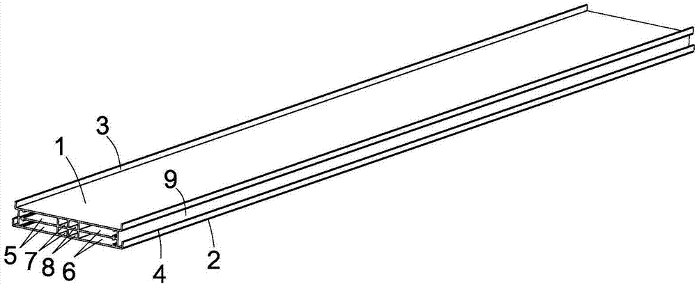
[0027] Such as figure 1 As shown, this embodiment discloses a double reflector for a base station antenna, including an upper U-shaped reflector with an upper reflective side plate, a lower U-shaped reflector with a lower reflective side plate, and an upper and lower U-shaped reflector. The cavity structure in the middle of the reflector; one end of the cavity structure abuts against the inner side of the upper U-shaped reflector, and the other end abuts against the inner side of the lower reflector; the upper U-shaped reflector and the lower U-shaped reflector The plate and the cavity structure are integrated with each other. By setting the upper reflector and the lower reflector, the reflector of the base station antenna has a smaller signal attenuation, which is better than 30db. This antenna is more concise in design, reduces assembly, and is easy to produce. save costs.

[0028] In the present invention, the reflection plate is a metal plate, and the signal is reflected ...

Embodiment 2

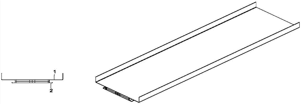
[0033] Such as figure 2 As shown, without affecting the size and appearance of the base station antenna, in order to save costs, the sizes of the upper and lower U-shaped reflectors can be different.

Embodiment 3

[0035] Such as image 3 As shown, in order to further increase the signal transmission capability of the base station antenna, the area of ​​the upper reflector is set to be larger than that of the lower emitter, and the height of the upper reflector is higher.


PUM


Abstract

The present invention relates to the mobile communication field, especially to a double-reflecting plate of a base station antenna. The double-reflecting plate of a base station antenna comprises an upper U-shaped reflecting plate (1) provided with an upper reflection side plate (3), a lower U-shaped reflecting plate (2) provided with a lower reflection side plate (4) and a cavity structure arranged between the upper U-shaped reflecting plate and the lower U-shaped reflecting plate. One end of the cavity structure is abutted with the inner side of the upper U-shaped reflecting plate (1), and the other end of the cavity structure is abutted with one end of the inner side of the lower U-shaped reflecting plate (2); and the upper U-shaped reflecting plate (1), the lower U-shaped reflecting plate (2) and the cavity structure mutually form integrated structures. The double-reflecting plate of the base station antenna disclosed by the invention allow the double-reflecting plate of the base station antenna to have the better front-to-rear ratio and more excellent signal emission through arrangement of the upper U-shaped reflecting plate (1), the lower U-shaped reflecting plate (2) and the cavity structure, the antenna design is more concise, assembling is reduced to facilitate production, and the cost is saved.

Description

technical field [0001] The invention relates to the field of mobile communication, and more specifically, to a double reflector for a base station antenna. Background technique [0002] With the development of mobile communications, the miniaturization of base station antennas is the direction of its development. The system communication capacity continues to increase, and the distance between base stations is getting smaller and smaller. In order to reduce the mutual interference between cells, an effective method is Improve the front-to-back ratio of the base station antenna, but after the antenna is miniaturized, it is difficult to guarantee the front-to-back ratio of the antenna because it is 30dB. Even with a good radiator, it is difficult to make the front-to-back ratio of the antenna better than 25dB, let alone better than 30dB. [0003] Chinese patent CN 105633594 A describes an antenna reflector (100), including a bottom plate (101); a pair of side plates (102a, 10...

Claims


Application Information

Patent Timeline
IPC IPC(8): H01Q15/14H01Q15/16
CPCH01Q15/14H01Q15/16
Inventor 维克托·亚历山德罗维奇·斯莱德科夫李梓萌
Owner GUANGZHOU SINAN ANTENNA DESIGN RES INSTCO
Learn More