Eureka AIR delivers breakthrough ideas for toughest innovation challenges, trusted by R&D personnel around the world.

Driving system of automobile lamp and driving method thereof

A driving system and a technology of automobile lamps, which are applied in the direction of lamp circuit layout, lighting devices, light sources, etc., can solve the problems of small efficiency and input voltage range, and can not solve the problems of LED module light efficiency attenuation and low efficiency. Achieve constant light effect

Inactive Publication Date: 2017-08-11
SHENZHEN HUAYAO LIGHT TECH CO LTD
View PDF0 Cites 1 Cited by
  • Summary
  • Abstract
  • Description
  • Claims
  • Application Information

AI Technical Summary

Problems solved by technology

The three driving methods have their own advantages and disadvantages. For example, the resistance current limiting scheme is suitable for low-efficiency applications, but it requires extremely high efficiency, and this method is not used in automotive lighting systems with a wide input voltage range; linear regulators only Suitable for low current or LED forward voltage drop slightly lower than the power supply voltage, but there are also problems with efficiency and small input voltage range; switching converters have the characteristics of flexible circuit topology, high efficiency and wide input voltage
[0003] Although the current mainstream automotive LED headlight drive circuits use switching converters, none of them can solve the problem of LED light efficiency attenuation due to long-term work of LED modules.

Method used

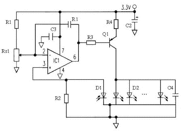

Image

  • Driving system of automobile lamp and driving method thereof
  • Driving system of automobile lamp and driving method thereof
  • Driving system of automobile lamp and driving method thereof

Examples


Embodiment Construction

[0011] The present invention provides a driving system and a driving method for automobile lamps. In order to make the object, technical solution and effect of the present invention clearer and clearer, the present invention will be further described in detail below with reference to the accompanying drawings and examples. It should be understood that the specific embodiments described here are only used to explain the present invention, not to limit the present invention.

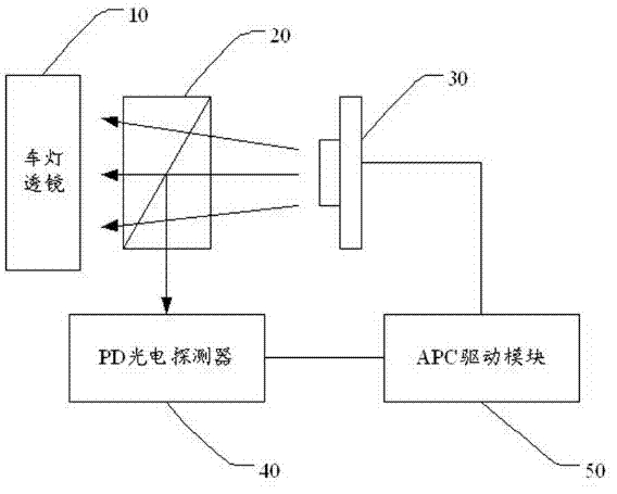
[0012] see figure 1 , the driving system of the automobile lamp provided by the present invention includes: the lamp lens 10, the prism 20, the LED array module 30, the PD photodetector 40 (high-speed photodetector) and the APC driving module 50 (produced by American Power Conversion Group driver module). Wherein, the vehicle light lens 10 is a vehicle headlight lens, the prism 20 is arranged between the vehicle light lens 10 and the LED array module 30 , and the PD photodetector 440 is located on one sid...


PUM


Abstract

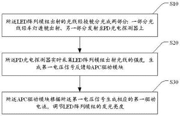
The invention discloses a driving system of an automobile lamp and a driving method thereof. The driving system comprises an automobile lamp lens, a prism, an LED array module group, a PD photoelectric detector and an APC driving module. The prism is arranged between the automobile lamp lens and the LED array module group. The PD photoelectric detector is arranged at one side of the prism. The light emitted by the LED array module group is split into two parts through the prism: one part of light is emergent through the automobile lamp lens, and the other part emits to the PD photoelectric detector. The PD photoelectric detector acquires the intensity of light emitted by the LED array module group in real time so as to generate a voltage signal to be fed back to the APC driving module. The APC driving module generates corresponding driving current according to the voltage signal to adjust the luminescent brightness of the LED array module group so that the luminous efficiency of the LED array module group is enabled to be constant without attenuation of the luminous efficiency caused by long-time working of the LED array module group.

Description

technical field [0001] The invention relates to the technical field of car lamp control, in particular to a driving system and a driving method for a car lamp. Background technique [0002] At present, the driving methods of LED lighting lamps can adopt three schemes: resistor current limiting, linear voltage regulator and switching converter. The three driving methods have their own advantages and disadvantages. For example, the resistance current limiting scheme is suitable for low-efficiency applications, but it requires extremely high efficiency, and this method is not used in automotive lighting systems with a wide input voltage range; linear regulators only It is suitable for low current or LED forward voltage drop slightly lower than the power supply voltage, but it also has the problems of efficiency and small input voltage range; switching converter has the characteristics of flexible circuit topology, high efficiency and wide input voltage. Therefore, considering ...

Claims


Application Information

Patent Timeline
Patent Type & Authority Applications(China)
IPC IPC(8): H05B37/02
CPCY02B20/40
Inventor 林家用柳立群
Owner SHENZHEN HUAYAO LIGHT TECH CO LTD
Why Eureka
Eureka Blog
Learn More