Minimal fluidflowmeter

A liquid flowmeter and tiny technology, applied in the field of flowmeters, can solve the problems of unstable running direction of the test gear and reduce the life of the test gear, and achieve the effect of stable direction and stable running direction.

Active Publication Date: 2017-08-15
威海坤科流量仪表股份有限公司
View PDF7 Cites 1 Cited by
  • Summary
  • Abstract
  • Description
  • Claims
  • Application Information

AI Technical Summary

Problems solved by technology

[0004] The purpose of the present invention is to solve the problem that the fluid entering the fluid test chamber through the fluid inlet will impact the intermeshing test gears inside the test chamber during the test of the existing micro liquid flowmeter, and the fluid will impact the test gear in a straight line through the fluid inlet. On the other hand, at the moment of impact, the direction of the impact force received by the test gear is scattered, and the running direction of the test gear will be very unstable. The test gears that mesh with each other will form frequent rotations in both positive and negative directions, and the running direction of the test gear will be very unstable. , It takes a period of time for the test gear to form a steady state operation. Such an impact will affect the test accuracy and reduce the life of the test gear. At the same time, it will also affect the technical problem of the life of the gear shaft and bearing. A tiny liquid flowmeter is provided in the test When the fluid enters the fluid test chamber through the fluid inlet, it will not impact the intermeshing test gears inside the test chamber, and the fluid will not directly impact the test gear through the fluid inlet, and the direction of the impact force on the test gear is stable. , the running direction of the test gear is stable, and the test gears meshing with each other will not form frequent rotations in both positive and negative directions. Tiny Liquid Flow Meters Affecting Gear Shaft and Bearing Life

Method used


Image

  • Minimal fluidflowmeter
  • Minimal fluidflowmeter
  • Minimal fluidflowmeter

Examples


Embodiment

[0018] The present invention will be further described below in conjunction with the examples.

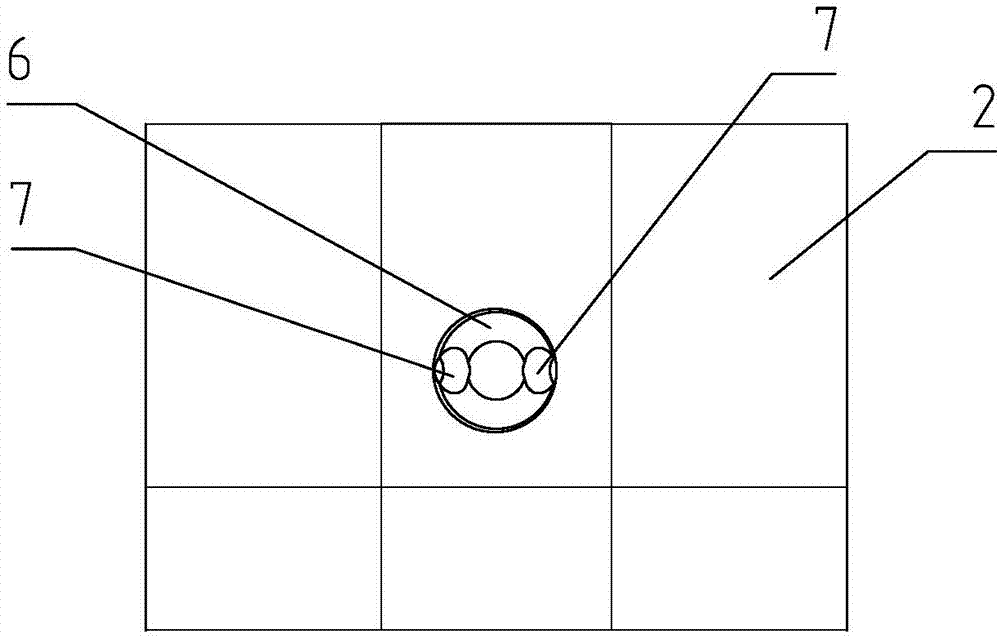
[0019] Figure 2-3 is an embodiment of the present invention, figure 2 It is an outline view of an embodiment of the present invention, in which it can be seen that the bottom of the fluid inlet 6 is provided with two fluid diversion inlets 7 .

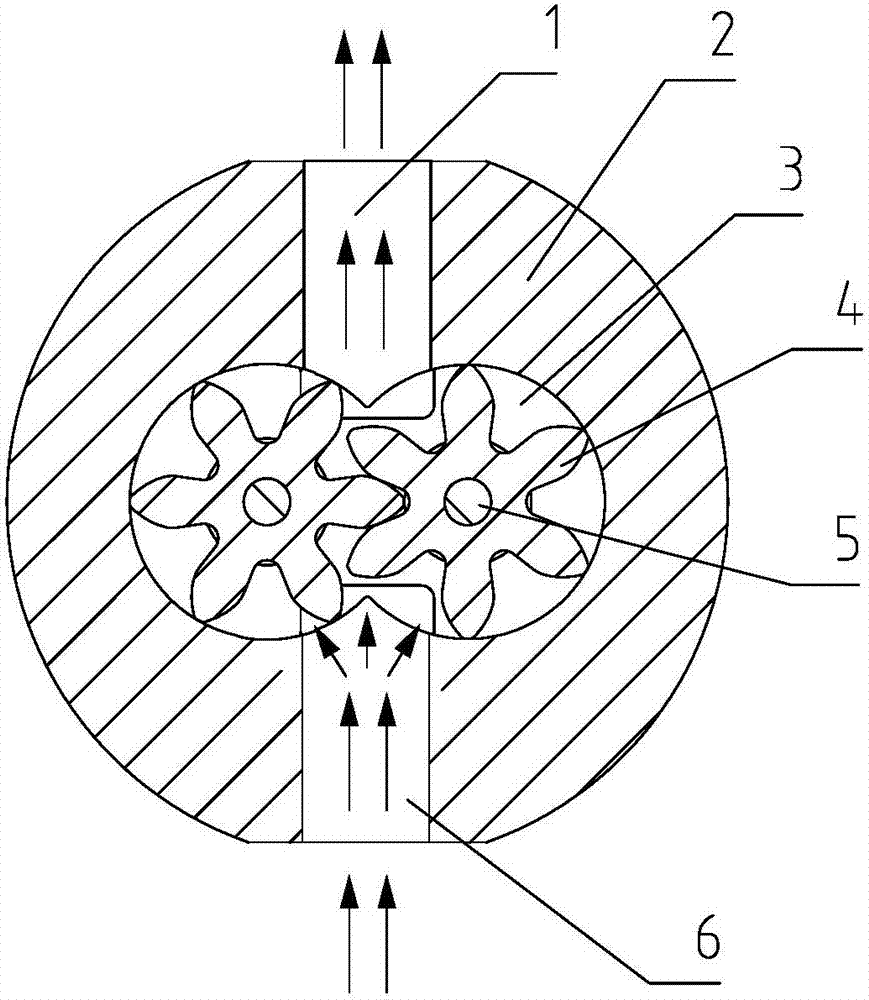
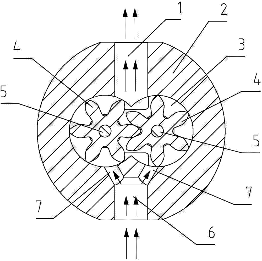
[0020] image 3 It is a cross-sectional view of an embodiment of the present invention. It can be seen from the figure that a tiny liquid flowmeter is provided with a housing 2, a fluid testing chamber 3 is provided inside the housing 2, and a fluid inlet 6 is provided on one side of the fluid testing chamber 3. The other side of the fluid test chamber 3 is provided with a fluid outlet 1, a pair of intermeshing test gears 4 are arranged inside the fluid test chamber 3, a fluid split inlet 7 is provided between the fluid inlet 6 and the fluid test chamber 3, and the fluid inlet The fluid split inlet 7 provided between the fluid test cha...


PUM


Abstract

The invention provides a minimal fluidflowmeter, and aims to solve existing problems; the revolve directions of testing gears an existing minimal fluidflowmeter are unstable in testing; the mutually engaged testing gears can form frequent rotations in forward and backward directions, and the testing gear revolve direction is very unstable; the testing gears need certain time to form stable revolution, such impact will affect the testing accuracy, thus reducing testing gear service life, and affecting gear shaft and bearing service life; the minimal fluidflowmeter can solve said problems, and is provided with a housing; a fluid testing cavity is arranged in the housing; one side of the fluid testing cavity is provided with a fluid inlet, and the other side of the fluid testing cavity is provided with a fluid outlet; a pair of mutually engaged testing gears are arranged in the fluid testing cavity; a fluid shunting inlet is arranged between the fluid inlet and the fluid testing cavity. The minimal fluidflowmeter can be widely applied to minimal fluid flow measurements.

Description

technical field [0001] The invention relates to a flow meter, in particular to a tiny liquid flow meter. Background technique [0002] As we know, the tiny liquid flowmeter is provided with a casing, and a fluid testing chamber is provided inside the casing, a fluid inlet is provided on one side of the fluid testing chamber, a fluid outlet is provided on the other side of the fluid testing chamber, and a fluid testing chamber is provided inside the fluid testing chamber. For intermeshed gears, when this micro liquid flowmeter detects the micro liquid flow, when the fluid enters the fluid test chamber, it pushes the intermeshed gears inside the fluid test chamber to rotate, and a gap is formed between the teeth of the intermeshed gears. Line seal, the outer circumference of the gear teeth and the inner wall of the fluid test chamber also form a line seal, and the flow rate of the fluid can be measured by testing the number of revolutions of the gear. [0003] When the existi...

Claims


Application Information

Patent Timeline
Patent Type & Authority Applications(China)
IPC IPC(8): G01F1/10
CPCG01F1/10
Inventor 高峻林国杰林永清
Owner 威海坤科流量仪表股份有限公司
Why Eureka
Try Eureka