Pressing and floating device for liner bushing

A floating device and bushing technology, which is applied in metal processing, metal processing equipment, manufacturing tools, etc., can solve the problems of increasing processing difficulty, increasing manufacturing cost, non-concentric bushing holes, etc., achieving high practicability and reducing manufacturing costs , Reduce the effect of processing difficulty

Pending Publication Date: 2017-08-18
ZHONGSHAN CLG AUTOMATION EQUIP
View PDF9 Cites 6 Cited by
  • Summary
  • Abstract
  • Description
  • Claims
  • Application Information

AI Technical Summary

Problems solved by technology

[0003] In the actual production process, workpieces with bushing holes often use cast-welded splices, resulting in deviations of bushing holes in different degrees and directions on the workpiece, resulting in the positioning mandrel of the existing press-in components and the workpiece. The phenomen

Method used


Image

  • Pressing and floating device for liner bushing
  • Pressing and floating device for liner bushing
  • Pressing and floating device for liner bushing

Examples


Embodiment Construction

[0024] Embodiments of the technical solutions of the present invention will be described in detail below in conjunction with the accompanying drawings. The following examples are only used to illustrate the technical solution of the present invention more clearly, and therefore are only examples, and should not be used to limit the scope of protection of this patent.

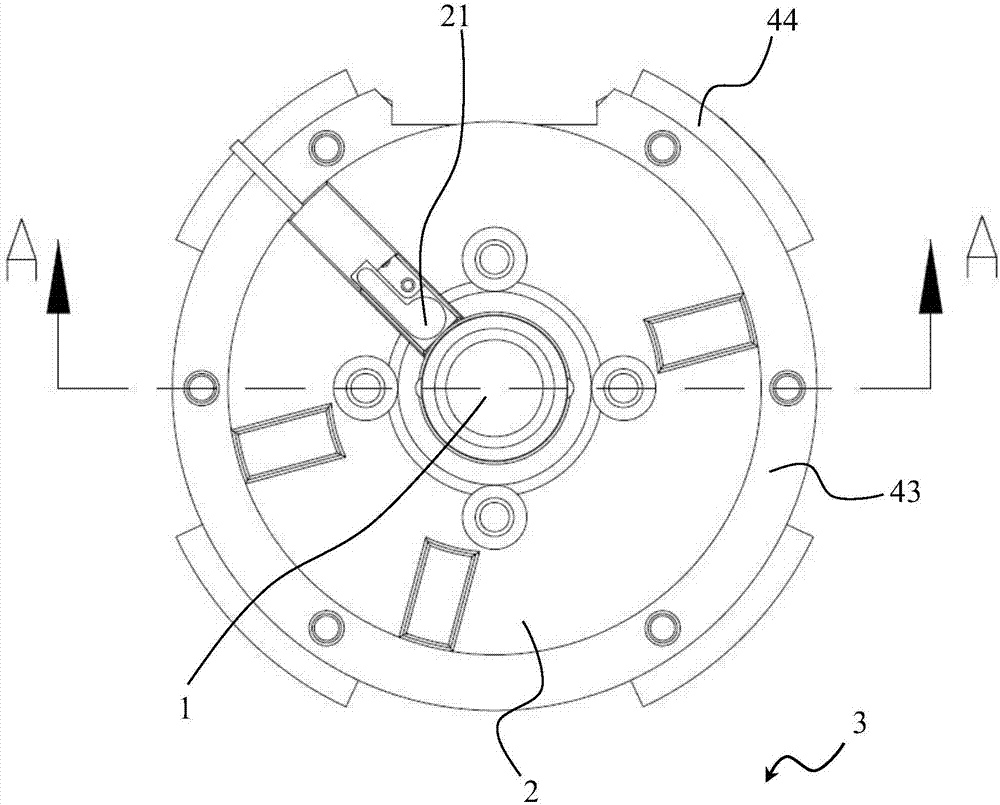
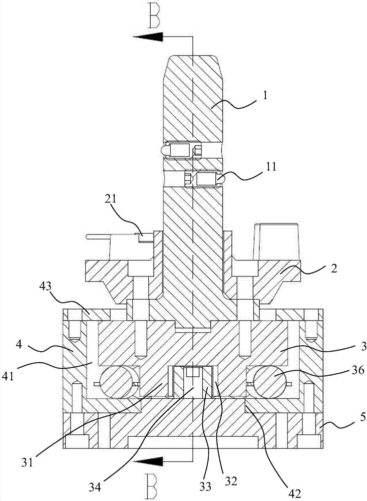
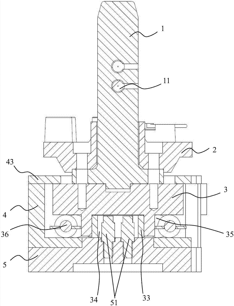
[0025] Such as Figure 1 to Figure 3 As shown, this embodiment discloses a bush press-in floating device, which includes a positioning mandrel 1 , a bush phase seat 2 , a sliding seat 3 , a fixed seat 4 and a bearing seat 5 . The bushing phase seat 2 is sleeved on the outside of the positioning mandrel 1, the bushing phase seat 2 and the positioning mandrel 1 are adapted, the bushing phase seat 2 and the positioning mandrel 1 are fixed on the upper end of the sliding seat 3 by bolts, the bushing The phase seat 2, the positioning mandrel 1 and the sliding seat 3 are concentric with each other. The middle part o...


PUM

PropertyMeasurementUnit
Diameteraaaaaaaaaa

Abstract

The invention discloses a pressing and floating device for liner bushing. The device comprises a positioning mandrel, a liner bushing phase position base, a sliding base, a fixed base and a bearing base, wherein the liner bushing phase position base is sheathed on the outer side of the positioning mandrel; the liner bushing phase position base and the positioning mandrel are fixed at the upper end of the sliding base by bolts; a sliding chamber is formed in a hollow part inside the fixed base and is placed in the sliding chamber; an annular boss is arranged in the middle part of the lower end of the sliding base; a longitudinal sliding chamber is arranged on the annular boss; a longitudinal sliding block is arranged in the longitudinal sliding chamber of the annular boss; a transverse sliding pin is fixedly mounted in the middle part of the upper end of the bearing base; and a transverse sliding groove matched with the transverse sliding pin is arranged at the lower end of the longitudinal sliding block. According to the device, the concentricity of the device and a liner bushing hole which is deviated on a workpiece can be realized, and then the liner bushing is pressed into the liner bushing hole which is deviated on the workpiece, so that scraps of the workpiece caused by deviation of the liner bushing are avoided, the machining difficulty of the liner bushing hole of the workpiece is reduced, and the manufacturing cost is reduced.

Description

technical field [0001] The invention relates to the technical field of press-fit assembly equipment for auto parts, in particular to a bush press-fit floating device. Background technique [0002] In the process of automobile production and manufacturing, it is often necessary to fit some bushes to existing workpieces. The operation is usually completed by a press-in device that can press the bushes into the bushing holes reserved on the workpiece. The existing bushing press-in device mainly includes: a mounting table for fixing a workpiece with a bushing hole, and a press-in assembly for pressing the bushing into the bushing hole. [0003] In the actual production process, workpieces with bushing holes often use cast-welded splices, resulting in deviations of bushing holes in different degrees and directions on the workpiece, resulting in the positioning mandrel of the existing press-in components and the workpiece. The phenomenon that the bushing hole is not concentric ma...

Claims


Application Information

Patent Timeline
IPC IPC(8): B23P19/12
CPCB23P19/12
Inventor 谢伟军谢毅伟陈天虎易栗卢俊业叶永太黄伟顺
Owner ZHONGSHAN CLG AUTOMATION EQUIP
Why Eureka
Try Eureka