
Shaft and bushing installation method

An installation method and shaft sleeve technology, applied in the field of machinery, can solve the problems of many equipment and large floor space.

Active Publication Date: 2019-02-15
河北大唐国际王滩发电有限责任公司
View PDF5 Cites 0 Cited by
  • Summary
  • Abstract
  • Description
  • Claims
  • Application Information

AI Technical Summary

Problems solved by technology

In the prior art, the steps of installation, detection and sorting of shafts and bushings are too long, and each step requires separate equipment to complete, resulting in more equipment required, too large floor space, and each step Human participation is required between these steps. For example, after the shaft and sleeve are installed, they need to be manually placed on the detection mechanism for detection (check whether the shaft sleeve is accurately installed on the specified position of the shaft, whether it is tilted or not) Irregular problems), and then classify the qualified and unqualified shafts during the detection process, so it is necessary to design a device that can realize the integration of installation, detection and sorting to solve the above problems

Method used


Image

  • Shaft and bushing installation method
  • Shaft and bushing installation method

Examples


Embodiment Construction

[0017] The present invention will be described in further detail below by means of specific embodiments:

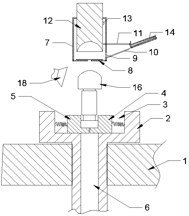
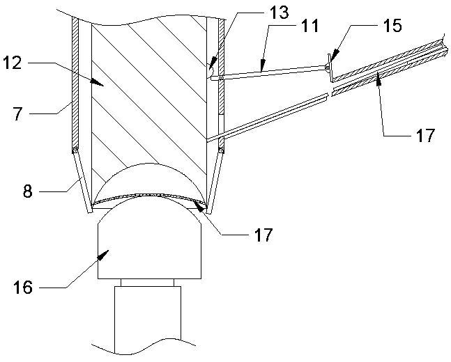
[0018] The reference signs in the accompanying drawings of the description include: base 1, mounting platform 2, mounting hole 3, fixing seat 4, fan-shaped block 5, screening channel 6, press-fitting cylinder 7, support plate 8, feed hole 9, transition Plate 10, linkage rod 11, pressure shaft 12, driving block 13, shaft sleeve conveying chute 14, baffle plate 15, shaft 16, shaft sleeve 17, detection mechanism 18.

[0019] The embodiment is basically as attached figure 1 Shown: the equipment that needs to be used in this method is a shaft sleeve installation device, and this shaft sleeve installation device includes a base 1, a shaft sleeve installation mechanism and a screening mechanism, and the base 1 is provided with a mounting table 2 for fixing the shaft 16, Mounting table 2 is provided with mounting hole 3, is provided with in the mounting hole 3 and is used for th...


PUM


Abstract

The invention relates to the field of machinery, in particular to a shaft and shaft sleeve mounting method. As a shaft sleeve placing method is limited in the method, on the one hand, the placing space of a shaft sleeve conveying chute can be saved, and on the other hand, the inclination of a shaft sleeve is increased; and when a baffle plate is opened, the shaft sleeve can quickly slide out from the shaft sleeve conveying chute. Through the linkage effect of a pressure shaft, a linkage rod and the baffle plate, the pressing and mounting process of the shaft sleeve and a shaft is realized, and meanwhile, the control of intermittent conveying of the shaft sleeve to a feed port of a pressing cylinder is also realized, so that the linkage effect of different ports is realized. Under the condition of having no need to move the shaft, the method can finish integral work of installation, detection and sorting of the shaft and the shaft sleeve.

Description

technical field [0001] The invention relates to the mechanical field, in particular to a method for installing a shaft sleeve. Background technique [0002] At present, shafts have been used in various fields of life. For some shafts, it is necessary to install a layer of plastic bushings on one end of the shaft to protect them from being worn out during transportation or handling. In the prior art, the steps of installation, detection and sorting of shafts and bushings are too long, and each step requires separate equipment to complete, resulting in more equipment required, too large floor space, and each step Human participation is required between these steps. For example, after the shaft and sleeve are installed, they need to be manually placed on the detection mechanism for detection (check whether the shaft sleeve is accurately installed on the specified position of the shaft, whether it is tilted or not) Irregular problems), and then classify the qualified and unqual...

Claims


Application Information

Patent Timeline
Patent Type & Authority Patents(China)
IPC IPC(8): B29C65/64B29C63/22B29C65/82B07C5/34
CPCB07C5/34B29C63/22B29C65/64B29C65/8276
Inventor 唐正权
Owner 河北大唐国际王滩发电有限责任公司
Learn More