High-resolution, nondestructive imaging of dielectric materials

a dielectric material, high-resolution technology, applied in the direction of dielectric property measurement, using reradiation, instruments, etc., can solve the problems of cord deterioration, prone to catastrophic failure, and defect can begin, so as to enhance the detection and location of defects, enhance the localization or imaging of features or irregularities, and improve the effect of slop

Active Publication Date: 2010-08-17
LITTLE JR JACK R
View PDF27 Cites 9 Cited by
  • Summary
  • Abstract
  • Description
  • Claims
  • Application Information

AI Technical Summary

Benefits of technology

[0028]I have discovered an improved method to enhance the detection and location of defects or other features in bulk dielectric materials. Monochromatic radiation, preferably microwave radiation, more preferably microwaves in the 5-50 gigahertz frequency range, is used to interrogate a sample. The microwaves are partly reflected at each defect or other feature where the dielectric constant changes (e.g., where there are delaminations, cracks, holes, impurities, thickness changes, other defects or structures of interest). A portion of the transmitted beam is combined with the signal reflected by the specimen being inspected. These two signals have the same frequency, but may differ in amplitude and phase. The signals combine to produce an interference pattern, a pattern that changes as the specimen changes, or as the position of the specimen changes relative to that of the detector. As illustrated in FIG. 2 (discussed in greater detail below), the interrogating radiation may be thought of as a sinusoidal (or quasi-sinusoidal) standing wave. The localization or imaging of features or irregularities is enhanced by exploiting the variation in distance resolution that results from the formation of a sinusoidal or quasi-sinusoidal standing wave. At certain characteristic distances, the standing wave has a high slope, and the amplitude of the wave varies strongly with small changes in distance. At other characteristic distances, the standing wave has a small or nearly zero slope, and the amplitude of the wave hardly varies with small changes in distance. See FIG. 2 and the discussion below. By conducting the inspection at distances where the amplitude of the standing wave varies strongly with small changes in distance, i.e., where the standing wave has a high slope, the resolution of detection or imaging is enhanced. By systematically varying the position of the transducer relative to the specimen, it is possible to create detailed images of the internal structure of the specimen across a selected range or ranges of depths. Defects and structures may be detected at smaller sizes than has previously been possible with microwave radiation. The resolution of the imaging is not limited by the wavelength of the interrogating radiation, but may be substantially smaller than that wavelength.
[0033]The distance between the end of the transducer and the near surface of the specimen under inspection will sometimes be referred to as the “stand-off.” The stand-off is illustrated, for example, in each of FIGS. 1 and 2. Changing the stand-off changes the amplitude and phase of the standing wave throughout the specimen. Changing the phase of the standing wave within the specimen changes the location of the regions of high sensitivity, ΔLH, and of low sensitivity, ΔLL, illustrated in FIG. 2. Therefore, by manipulating the stand-off distance, it is possible to optimize the detection sensitivity at a selected narrow range of depths within the specimen.
[0034]There can be ambiguity in interpreting an interferometric signal, as points within the specimen that are spaced an integral number of half-wavelengths apart may not initially be distinguished from one another, due to the identical phase of the waves reflected from such points (where the wavelength in question is that within the material, which generally differ from the wavelength in air or vacuum, depending on the index of refraction). However, if a frequency is chosen to reduce the number of wavelengths needed to traverse the thickness of the specimen, one may enhance the sensitivity at a selected depth range with minimal ambiguity. In the special case where the specimen thickness is less than (preferably substantially less than) half the wavelength, then the imaging may be optimized for a single, very narrow band of the thickness within the specimen.

Problems solved by technology

Thus when such a joint fails, it is prone to catastrophic failure.
A defect can begin, for example, when a small crack allows moisture inside the rubber.
The moisture can cause the cord to deteriorate, which can lead to adjacent layers delaminating from one another.
Defects such as these inside a joint are difficult to detect nondestructively through conventional means.
However, ultrasonic inspection cannot be used for rubber or soft plastic, because the polymers absorb nearly all sound energy, and reflect essentially none.
The mesh or fabric of a composite material so highly scatters and disperses the ultrasonic waves that an extremely noisy reflection results.
Eddy current measurements or magnetic measurements do not work well in rubber either, because rubber does not conduct electricity.
Under most operating conditions the most common flaw leading to failure is delamination.
Durometers have poor practical utility, but they are nevertheless commonly used in the non-destructive testing of rubber joints.
Irregularities in the strength of the received signal were correlated with cracks or other flaws in the propellant.

Method used


Image

  • High-resolution, nondestructive imaging of dielectric materials
  • High-resolution, nondestructive imaging of dielectric materials
  • High-resolution, nondestructive imaging of dielectric materials

Examples


Embodiment Construction

[0040]Substances such as fiberglass that produce noisy reflection patterns in prior ultrasonic techniques may be inspected at low noise levels with the novel microwave technique. For example, the novel technique readily detects many common defects in fiberglass.

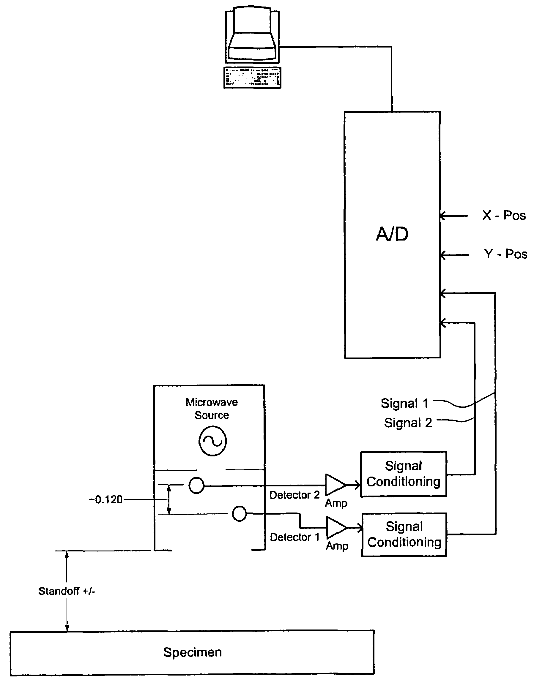
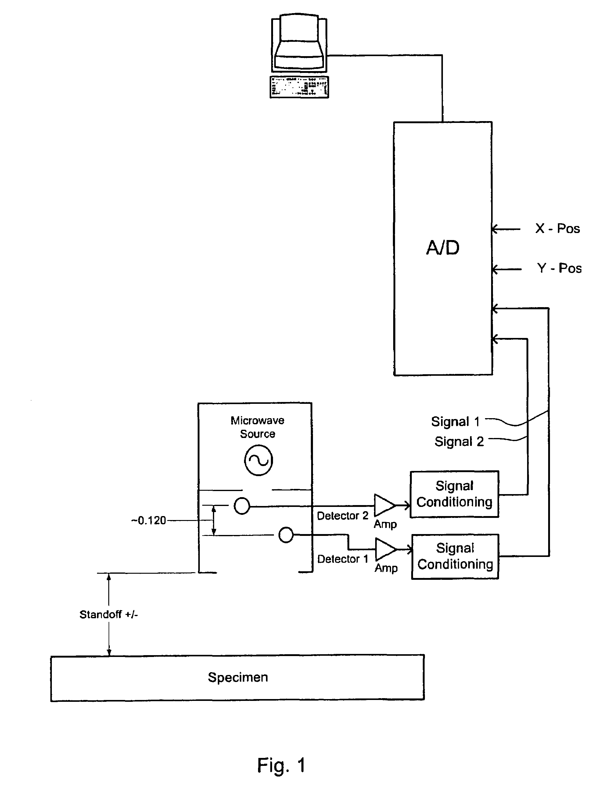
[0041]There are many potential fields of use for the invention. As one illustration, the invention may be used to inspect fiber-reinforced plastic (FRP) pipe. Commercially available FRP pipe is a complex composite structure, typically containing many layers of varying composition, density, and dielectric constant. When microwaves are directed towards an FRP pipe, reflections return from all interfaces between materials of different dielectric constant. The returning signal is thus a superposition of many different waveforms, essentially identical in frequency, but generally differing in phase and amplitude. In general, the full thickness of the material is inspected, and all interfaces upon which the microwaves impinge contri...


PUM

PropertyMeasurementUnit
thickaaaaaaaaaa
thickaaaaaaaaaa
thickaaaaaaaaaa

Abstract

The enhanced detection of defects in the bulk dielectric material (Specimen) having radiation partly reflected at interfaces where the dielectric constant changes (e.g., where there are defects or structures). A sinusoidal or quasisinusoidal wave (Microwave Source) results. Localization or imaging of features is enhanced by exploiting the variation in distance resolution (Standoff+ / −) in a sinusoidal or quasi-sinusoidal standing wave. At characteristic distances, the wave has a high slope and the amplitude of the wave varies strongly with small changes in distance (Standoff+ / −). By inspecting at these characteristic distances (Standoff+ / −), the resolution is enhanced. By systematically varying the position of the transducer or specimen, detailed images may be formed of the internal structure of the specimen across a range of depths. Defects and structures may be detected at smaller sizes than has previously been possible.

Description

[0001]The benefit of the 5 Aug. 2004 filing date of U.S. provisional patent application Ser. No. 60 / 598,989 is claimed under 35 U.S.C. §119(e) in the United States, and is claimed under applicable treaties and conventions in all countries.TECHNICAL FIELD[0002]This invention pertains to an apparatus and method for the enhanced interferometric localization of irregularities in bulk dielectric materials.BACKGROUND ART[0003]There is an unfilled need for improved, nondestructive means to test bulk dielectric materials for flaws, defects, irregularities, and other features; particularly to determine the three-dimensional location and profile of flaws, defects, irregularities, and other features below the accessible surface of dielectric materials. Additionally, there is an unfilled need to determine the internal, detailed structure of a specimen across a narrow range of depths. For example, there is an unfilled need for improved, nondestructive means for examining dielectric materials in ...

Claims


Application Information

Patent Timeline
Patent Type & Authority Patents(United States)
IPC IPC(8): G01N22/02
CPCG01N22/00G01S13/32G01S13/89G01R27/267
Inventor LITTLE, JR., JACK R.
Owner LITTLE JR JACK R
Why Eureka
Try Eureka