
Tooth for circular saw or mower drum

Inactive Publication Date: 2014-09-18
PRENBEC EQUIP
View PDF8 Cites 7 Cited by
  • Summary
  • Abstract
  • Description
  • Claims
  • Application Information

AI Technical Summary

Benefits of technology

The present invention provides a tooth with an non-linear and diverging outer side, which increases the transversal clearance of the tooth and allows for a greater kerf at both ends. This design increases the life of the disk while remaining cost-effective.

Problems solved by technology

However, increasing the height of the tooth also increases the stress and load applied on the rotating disk, resulting in energy losses.
Indeed, a longer tooth tends to increase the wear and tear of the disk, since the impact on the cutting edge of the tooth occurs further away from the periphery of the disk (i.e. the radial distance between the point of impact of the tooth and the center of the disk is greater), thereby increasing stress on the rotating disk.
Another solution consists in machining the rotating disk so that the outer side of tooth extends slightly more outwardly, with an “open angle”, which can also increase the side clearance of the tooth and holder, but can tend to tear the tooth off the rotating disk.
Such an outwardly affixed tooth also tends to increase the stress on the tooth because the tooth tends to be “ripped-off” due to an increased moment resulting from the outwardly-disposed tooth.

Method used


Image

  • Tooth for circular saw or mower drum
  • Tooth for circular saw or mower drum
  • Tooth for circular saw or mower drum

Examples


first embodiment

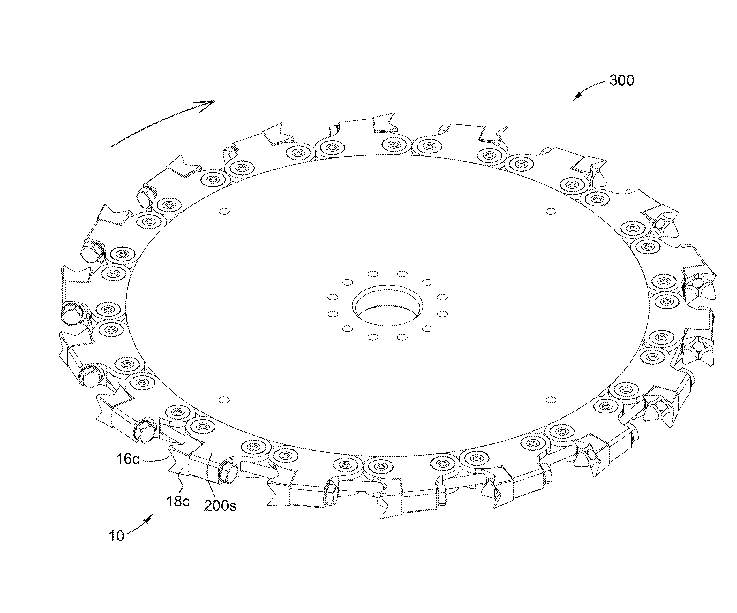
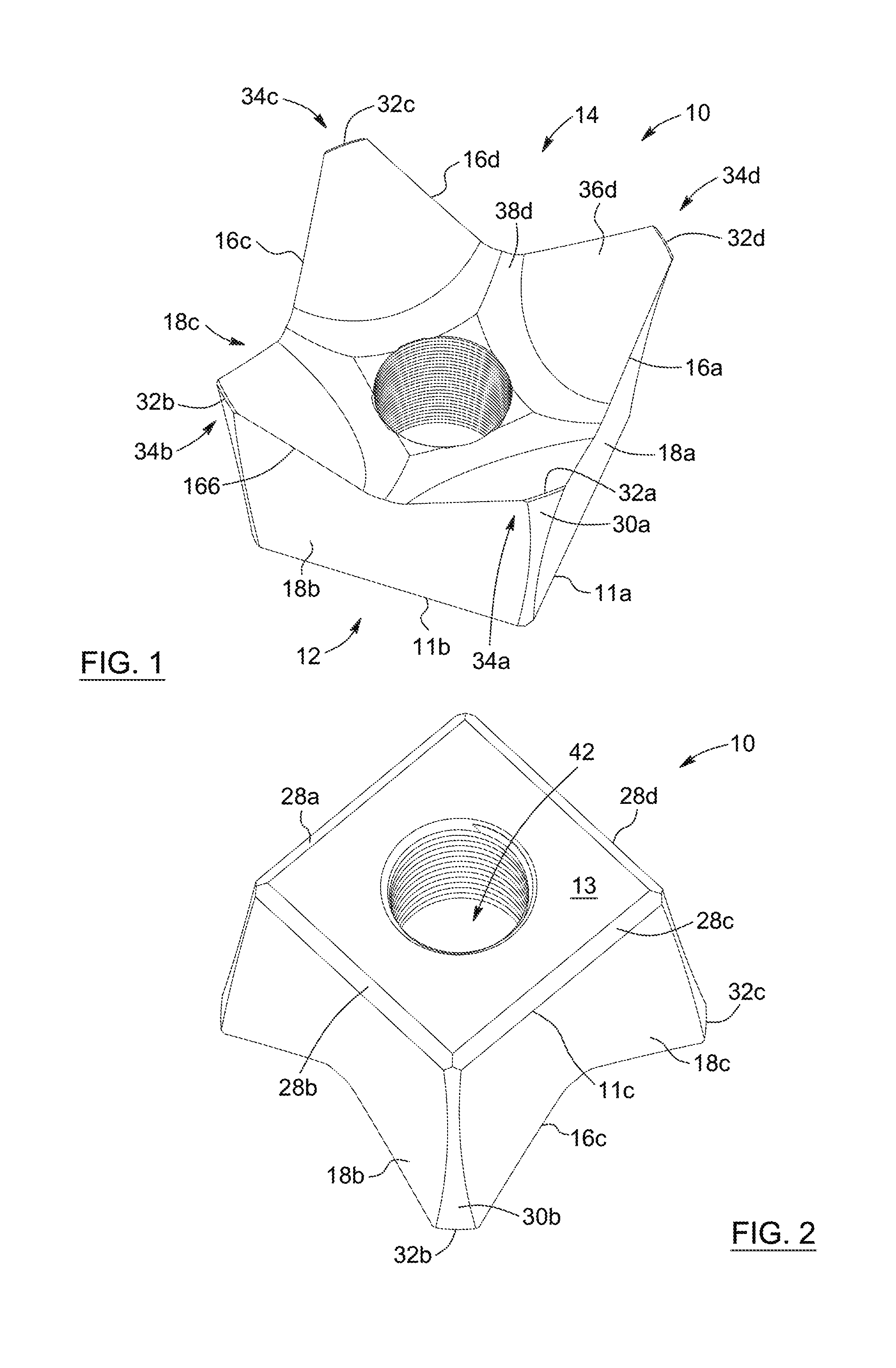
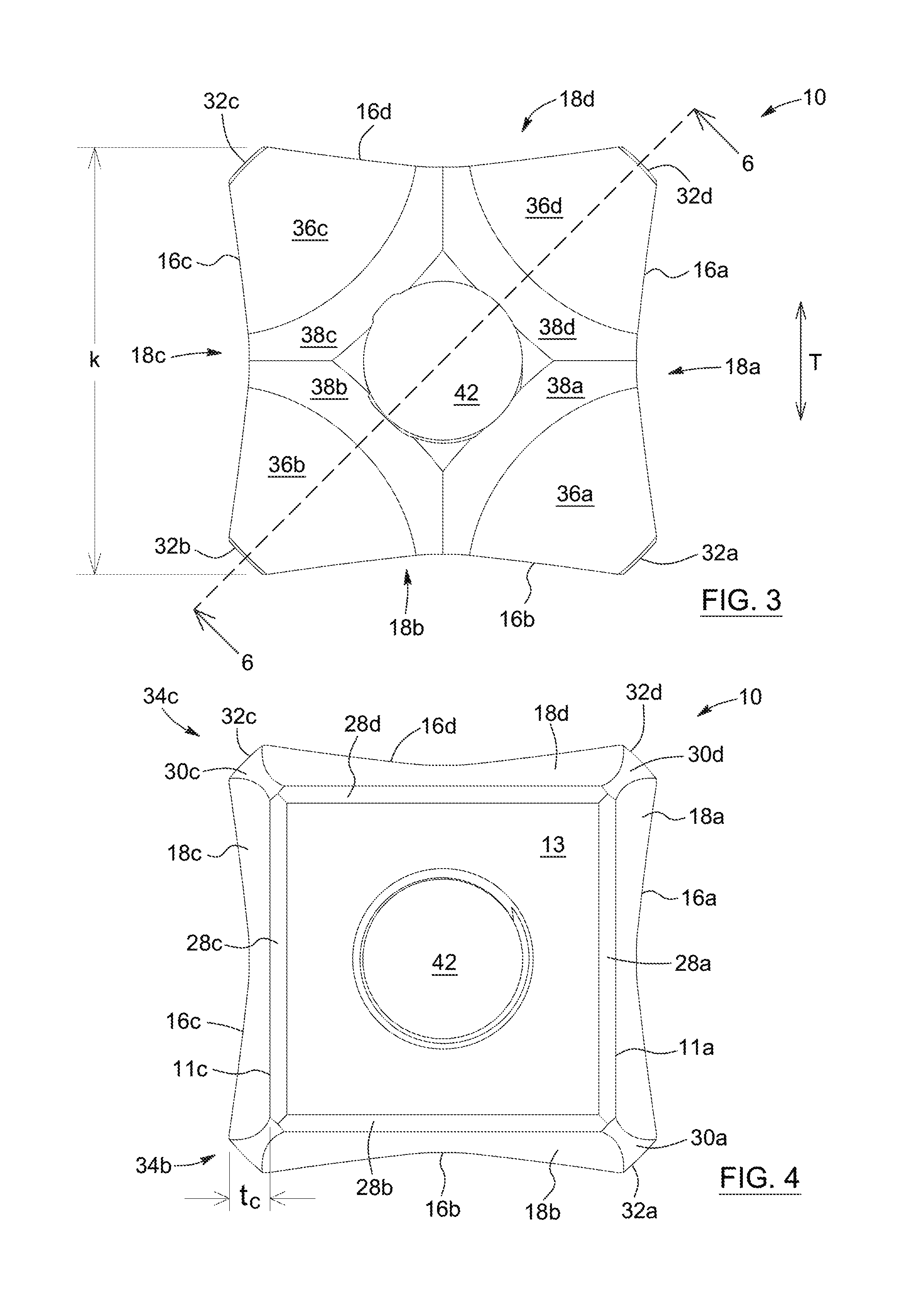
[0080]Referring to FIGS. 1 to 6, a tooth 10 is shown. The tooth 10 can be used on machinery for cutting and felling trees, such as a circular saw 300, as shown in FIG. 9. Alternatively, the tooth can be used on equipment for clearing brushwood, such as a mower drum 400, as show in FIG. 10.

[0081]Referring to FIGS. 1 to 10, the saw tooth 10 is mountable onto the holder 200 of a circular saw 300 or of a mower drum 400, the holder 200 being either integrally part of the saw or drum, or detachable.

[0082]The tooth 10 has a mounting end 12, a cutting end 14 and several sides 18. The mounted end 12 is for mounting against a component 202 of the holder 200. The cutting end 14 is opposite to the mounting end 12, and is provided with at least one cutting edge 16.

[0083]The sides 18 extend from the mounting end 12 to the cutting end 14. The tooth 10 includes at least one holder side 18a, which is operatively mountable against the holder 200 and at least one outer side 18c, which is opposite to ...

second embodiment

[0105]FIG. 20 also better shows how the cutting tips and cutting edge of the tooth extend beyond the mounting end, providing an increased clearance tc compared to a tooth of similar height, but with a linear outer side. Of course, it can be considered to mount the tooth 110 to this variant of the saw 2300. In this case, the lower segment 120i of the tooth 110 would closely fit the shoulder portion 2204 of the holder. In FIG. 20, a prior art, straight side tooth 8 is shown in stippled lines. As can be appreciated, when comparing the tooth 10 versus the prior art tooth 8, the clearance provided between the tip of the tooth 10 and the mounting end and holder side is greater than for the tooth 8. The tooth 10 is also slightly smaller in height compared to the tooth 8. Such slight differences provide non-trivial advantages, especially for high speed / high energy applications.

[0106]An advantage of such characteristics of the curved holder side of the tooth is that the mounting of the tooth...


PUM

PropertyMeasurementUnit
Lengthaaaaaaaaaa
Lengthaaaaaaaaaa
Angleaaaaaaaaaa

Abstract

A saw tooth for mounting onto a holder of a circular saw or of a mower drum is provided. The tooth has a mounting end for mounting against a component of the holder, a cutting end, opposite to the mounting end, the cutting end being provided with at least one cutting edge; and a plurality of sides extending from the mounting end to the cutting end. The plurality of sides include at least one holder side operatively mountable against the holder and at least one outer side opposite to the holder side the outer side being non-linear, diverging from the mounting end to the cutting end and having a contour slope which increases from the mounting end to the cutting end. The tooth thereby provides a greater clearance at its mounting end, and a greater kerf at its cutting end.

Description

FIELD OF THE INVENTION[0001]The present invention relates to the field of tree felling and, more particularly, relates to a tooth for a circular saw or a mower drum.BACKGROUND[0002]Tree felling machines typically include a circular saw disk which rotates at high speed. The saw disk has several teeth mounted on holders all around its periphery. The saw disk is moved horizontally through the tree, and as it advances, it creates a kerf or cut in the trunk of the tree.[0003]A tooth for a circular saw generally has a mounting end and a cutting end and four sides diverging out from the mounting to the cutting end. The four sides are identical with a straight, linear profile. The cutting end is provided with four pointed tips at its corners, and four cutting edges extend between the cutting tips.[0004]In the field of tree felling, the kerf refers to the width of the cut made by a saw in the trunk of the tree. The kerf of a typical four-sided tooth is thus the width of either one of the cut...

Claims


Application Information

Patent Timeline
IPC IPC(8): B27B33/12
CPCB27B33/12Y10T83/9319
Inventor MACLENNAN, CHARLESMACLENNAN, ROBERTRIOUX, DENISLAROUCHE, STEPHANE
Owner PRENBEC EQUIP
Learn More