Lateral-inflow and rolling-energy-dissipation bank spillway

A spillway and energy dissipation technology, applied in coastline protection, water conservancy engineering, marine engineering and other directions, can solve the problems of large amount of excavation works and the inability to dissipate energy by water flow at the entrance of the spillway, and achieve the effect of reducing difficulty

Inactive Publication Date: 2013-07-10
SICHUAN UNIV
View PDF2 Cites 7 Cited by
  • Summary
  • Abstract
  • Description
  • Claims
  • Application Information

AI Technical Summary

Problems solved by technology

[0006] Aiming at the problems existing in the traditional spillway inlet part of the prior art, the purpose of the present invention is to provide a side flow swirling energy-dissipating bank spillway that subverts the form of the traditional spillway inle

Method used


Image

  • Lateral-inflow and rolling-energy-dissipation bank spillway
  • Lateral-inflow and rolling-energy-dissipation bank spillway
  • Lateral-inflow and rolling-energy-dissipation bank spillway

Examples


Embodiment 1

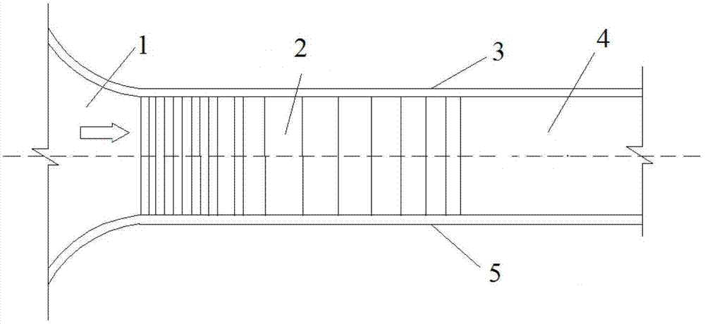
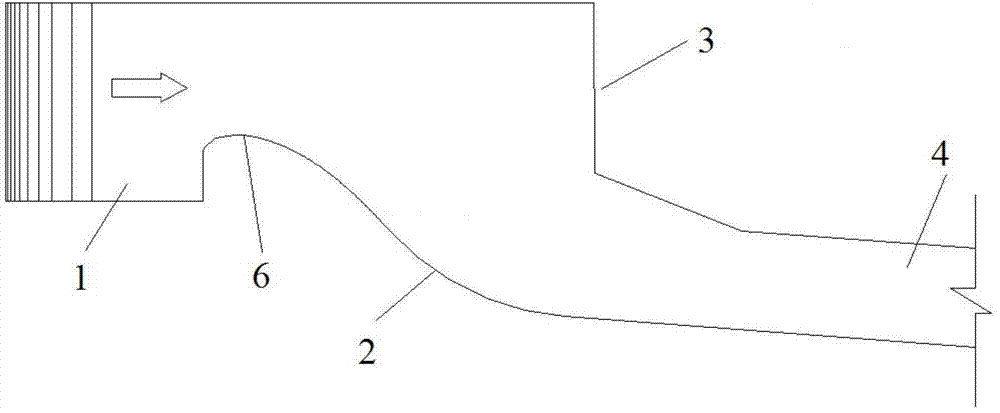
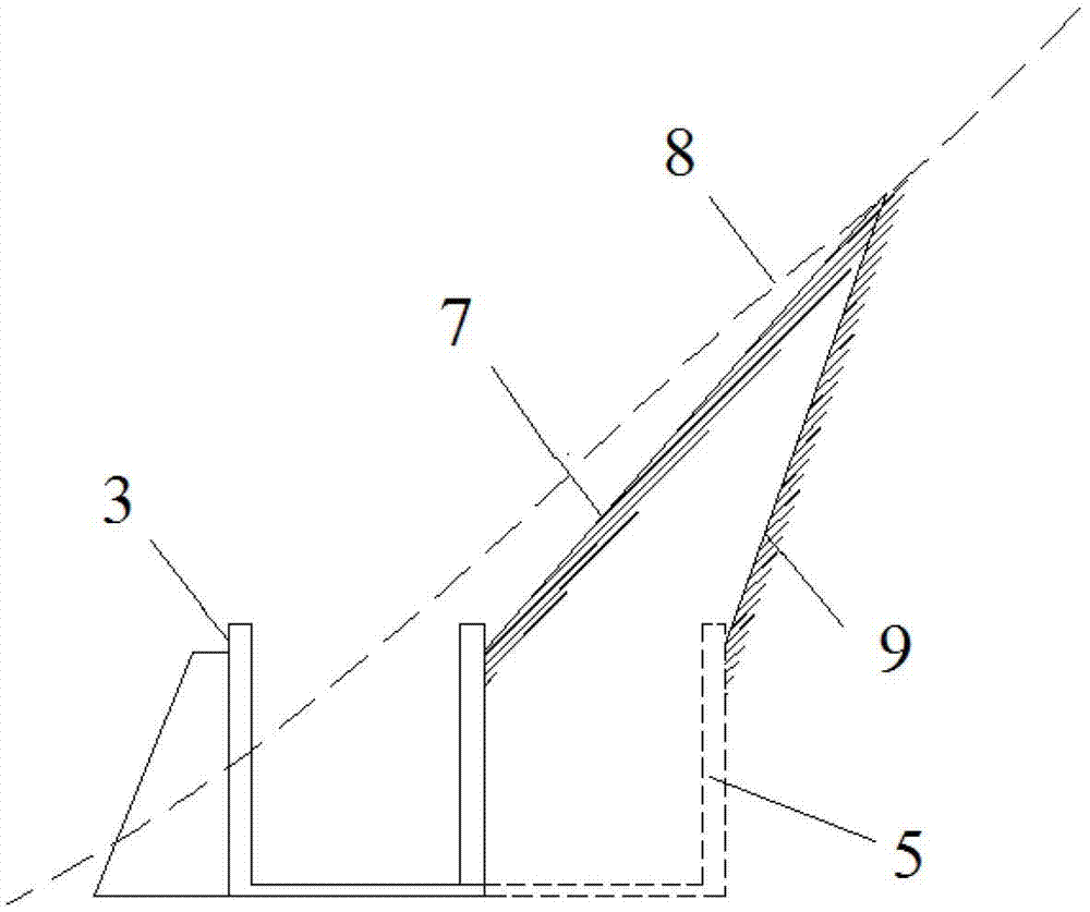
[0024] The structure of the lateral inflow swirl and energy dissipation bank spillway in this embodiment is as follows: diagram 2-1 , 2-2 , 2-3, including the spillway inlet part, the spillway chute 4 and the spillway flood discharge and energy dissipation outlet part, the axis of the spillway inlet part intersects the axis of the spillway chute at an angle of about 75 degrees, and the spillway inlet part includes a section of diversion channel , WES utility weir section 2 and the side channel 12 composed of WES utility weir, flat-bottomed trough bottom and the vertical side wall 13 on the opposite side of the spillway inlet to allow the water flow to roll into the spillway discharge channel, and the weir whose bottom of the diversion channel is lower than the WES utility weir and connected to the weir crest of the WES utility weir through vertical steps, and the edge of the weir bottom of the WES utility weir is aligned with the side wall 13 on the same side as the spillway ...


PUM


Abstract

The invention discloses a lateral-inflow and rolling-energy-dissipation bank spillway which comprises a spillway inlet portion, a spillway discharge chute and a spillway energy-dissipating and discharging outlet portion. The spillway inlet portion comprises an approach channel section and a WES (waterway experiment section) practical weir section, the axis of the spillway inlet portion is intersected with the axis of the spillway discharge chute at an angle of not less than 45 degrees, and a lateral chute which is composed of a WES practical weir, a chute bottom and an opposite side wall of a spillway inlet is designed behind the WES practical weir section and enables waterflow to rollingly enter the spillway discharge chute. The mode of bank spillway inlet portion of the lateral-inflow and rolling-energy-dissipation bank spillway is a complete change for the mode of a traditional bank spillway inlet portion, so that a series of problems such as the engineering quantity of the excavation of transverse and longitudinal mountain of the inlet is large and that the spillway inlet portion cannot dissipate the energy of the waterflow in the traditional spillway inlet portion can be solved.

Description

technical field [0001] The invention belongs to the technical field of flood discharge and energy dissipation for a spillway of a water conservancy and hydropower project, and in particular relates to a bank spillway with a lateral inflow swirl and energy dissipation. Background technique [0002] In water conservancy and hydropower projects, in order to protect the safety of dams and equipment during flood seasons, barrage dams are designed with spillways. For the shore spillway, it is composed of the upstream inlet part of the spillway where the discharge water enters the spillway, the spillway chute part and the downstream energy dissipation outlet part of the spillway. WES utility weir section. In the design form of the upstream entrance of the traditional spillway, the direction of the spillway entrance is consistent with the direction of the spillway chute, and the spillway chute is next to the WES utility weir that constitutes the spillway entrance, and the water flo...

Claims


Application Information

Patent Timeline
IPC IPC(8): E02B8/06
Inventor 邓军许唯临刘善均曲景学王韦张建民田忠张法星卫望汝
Owner SICHUAN UNIV
Why Eureka
Try Eureka