
Handle mounting structure

A technology for installing structure and handle, which is applied in the direction of control device, transportation and packaging, vehicle parts, etc., can solve the problems of inconvenient installation and disassembly of handle, shield and shift lever, and achieve the effect of convenient disassembly and assembly and reliable cooperation.

Active Publication Date: 2017-08-18
ANHUI JIANGHUAI AUTOMOBILE GRP CORP LTD
View PDF5 Cites 0 Cited by
  • Summary
  • Abstract
  • Description
  • Claims
  • Application Information

AI Technical Summary

Problems solved by technology

[0004] The invention provides a handle installation structure in order to solve the problem of inconvenient installation and disassembly of the handle, shield and shift lever in the prior art

Method used


Image

  • Handle mounting structure
  • Handle mounting structure
  • Handle mounting structure

Examples


Embodiment Construction

[0025] In order to enable those skilled in the art to better understand the technical solutions of the present invention, the present invention will be further described in detail below in conjunction with the accompanying drawings.

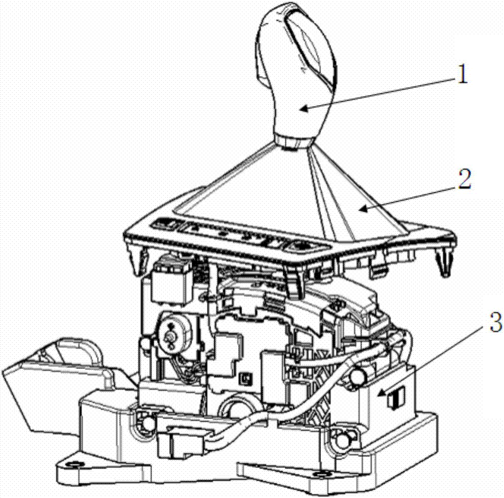
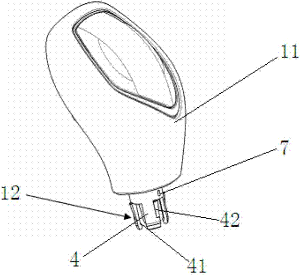
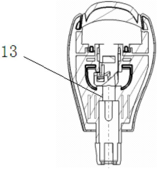
[0026] Such as Figure 1 to Figure 7 As shown, a handle installation structure provided by the embodiment of the present invention includes a shift handle 1, a shield assembly 2, and an operating mechanism 3. The operating mechanism 3 includes an operating mechanism body 31 and a shift lever 32, wherein, in this In the scheme, the shift handle 1 includes a handle body and a cylindrical insertion part 12 arranged at the bottom of the handle body. The cylindrical insertion part is surrounded by a plurality of claws 4 arranged at intervals. The shift lever 32 is plugged and fitted, and the top of the shift lever 32 is plugged into the cylindrical socket; that is, the assembly of the shift lever and the handle is facilitated by the plug-in assembly. ...


PUM


Abstract

The invention discloses a handle mounting structure which comprises a gear shifting handle, a shield assembly and a control mechanism, wherein the control mechanism comprises a control mechanism body and a gear shifting rod; the gear shifting handle comprises a handle body and a cylindrical inserting part arranged at the bottom of the handle body, and the cylindrical inserting part is enclosed by a plurality of claws which are arranged at intervals; the outer side of the bottom end of each claw is respectively provided with a bulge; the shield assembly comprises an upper shield clip, a lower shield clip and a shield shell; the inner wall of the upper shield clip is provided with a plurality of guide limiting grooves which are longitudinally arranged at intervals, and the inner wall between adjacent guide limiting grooves serves as a driving part; and the bulges are positioned in the guide limiting grooves, the bulges can slide out of the guide limiting grooves by rotating the upper shield clip, and the driving parts and the bulges are in force fit and can drive the cylindrical inserting part to realize radial shrinkage. Matched fixation of the claws with the gear shifting rod and the shield assembly is realized; during dismounting, the upper shield clip is reversely rotated; and the dismounting and mounting processes are convenient, and the connection is reliable.

Description

technical field [0001] The invention relates to the field of fixed installation of vehicle handles, in particular to a handle installation structure. Background technique [0002] The shift handle is installed in the cab of the car, connected with the shift lever, and assembled on the control mechanism to enable the driver to realize the shift function. During use, the handle may be replaced and disassembled due to surface wear or modification, and may also be disassembled due to damage and replacement of other parts. [0003] The traditional installation structure of the handle is the clamp locking type, that is, the shift lever is inserted into the shift handle, the plastic rib protruding from the handle slides into the metal groove of the shift lever, and the matching position is locked with a clamp. The assembly efficiency is low, and it is not easy to disassemble during vehicle maintenance. And the guard cover is compressed on the handle and cannot be disassembled, th...

Claims


Application Information

Patent Timeline
Patent Type & Authority Applications(China)
IPC IPC(8): B60K20/02
CPCB60K20/02
Inventor 焦红莲王志强赖燕斌王涛程建羊于尧杨标
Owner ANHUI JIANGHUAI AUTOMOBILE GRP CORP LTD
Learn More