
Anti-disengagement limiting type hub mounting structure

An installation structure and anti-loosening technology, applied to spoke wheels, wheels, transportation and packaging, etc., can solve the problems of large inertial resistance, complex manufacturing process, poor heat dissipation, etc., to ensure the stability of contact, ingenious structural design, Realize the effect of radial shrinkage

Inactive Publication Date: 2021-06-25
江苏鑫晟发科技有限公司
View PDF0 Cites 1 Cited by
  • Summary
  • Abstract
  • Description
  • Claims
  • Application Information

AI Technical Summary

Problems solved by technology

The main advantages of steel wheels are simple manufacturing process, relatively low cost, and strong resistance to metal fatigue; but the disadvantages are also obvious, such as large weight, large inertial resistance, poor heat dissipation, etc.; the advantages of alloy wheels are light weight, easy to manufacture High precision, high strength, small inertial resistance, strong heat dissipation, good visual effects, etc.; the disadvantage is that the manufacturing process is complicated and the cost is high
However, the disadvantages of the wheel hubs in the prior art are: whether it is an alloy wheel hub or a steel wheel hub, they are integrally formed, and it is inconvenient to disassemble the rim; If the size is slightly deviated, it will be difficult for the outer end of the spoke to connect to the inner side of the rim, which makes the whole structure inflexible and greatly limited in use. It is necessary to develop a spoke that can quickly and conveniently fine-tune the position to reach the position connected to the rim and improve The assembly flexibility of the structure needs to ensure the stability of the structure at the same time

Method used

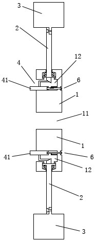

Image

  • Anti-disengagement limiting type hub mounting structure
  • Anti-disengagement limiting type hub mounting structure
  • Anti-disengagement limiting type hub mounting structure

Examples


Embodiment Construction

[0019] The content of the present invention will be further described in detail below in conjunction with the accompanying drawings.

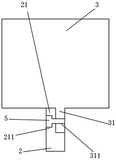
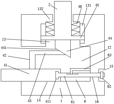
[0020] Such as Figures 1 to 4 As shown, an anti-off-limiting wheel hub installation structure includes a rim 3, a central disk 1, a spoke 2, a synchronous drive assembly 4, and an anti-off-positioning assembly 6; the rim 3 is installed around the outer side of the center disk 1; The central disk 1 and the rim 3 are concentrically arranged; the center of the central disk 1 is provided with an axle mounting hole 11; a plurality of spokes 2 are evenly installed on the outer sides of the central disk 1; the inner and outer ends of the plurality of spokes 2 are respectively Connected between the central disk 1 and the rim 3; one side of the central disk 1 is provided with a ring-shaped driving groove 12; the inner side of the driving groove 12 is provided with a threaded ring surface 14; the driving groove 12 A plurality of connecting grooves 13 a...


PUM


Abstract

The invention discloses an anti-disengagement limiting type hub mounting structure which comprises a rim, a center disc, spokes, a synchronous driving assembly and an anti-disengagement limiting assembly. The anti-disengagement limiting assembly is additionally arranged, the inner end of an anti-disengagement screw rod is rotationally clamped in a rotary clamping ring groove in the inner end of a driving internal thread ring, due to limiting of the anti-disengagement screw rod, the driving internal thread ring cannot be separated from the driving groove no matter how the driving internal thread ring rotates, and it is guaranteed that the driving internal thread ring cannot fall off; and after rotation adjustment of the driving internal thread ring is completed, a locking nut is rotationally connected with the inner wall of a locking groove in an abutting mode, so that the anti-disengagement screw rod and the driving internal thread ring are limited by the locking nut and cannot move towards the outer portion of one side of the center disc, and the abutting stability of the driving internal thread ring and the driven block is ensured.

Description

technical field [0001] The invention relates to an anti-off and position-limiting wheel hub installation structure. Background technique [0002] In the prior art, the wheels on the market can be divided into two categories: steel wheels and alloy wheels according to their materials. The main advantages of steel wheels are simple manufacturing process, relatively low cost, and strong resistance to metal fatigue; but the disadvantages are also obvious, such as large weight, large inertial resistance, poor heat dissipation, etc.; the advantages of alloy wheels are light weight, easy to manufacture High precision, high strength, small inertial resistance, strong heat dissipation, good visual effects, etc.; the disadvantage is that the manufacturing process is complicated and the cost is high. However, the disadvantages of the wheel hubs in the prior art are: whether it is an alloy wheel hub or a steel wheel hub, they are integrally formed, and it is inconvenient to disassemble...

Claims


Application Information

Patent Timeline
Patent Type & Authority Applications(China)
IPC IPC(8): B60B1/04B60B1/02
CPCB60B1/02B60B1/042
Inventor 唐建
Owner 江苏鑫晟发科技有限公司
Learn More