
Air spring drum

A technology of air springs and drum plates, which is applied to tires, other household appliances, household appliances, etc., can solve the problems of poor performance of air spring drums, and achieve the effect of solving poor performance

Pending Publication Date: 2022-02-18
MESNAC +1
View PDF0 Cites 0 Cited by
  • Summary
  • Abstract
  • Description
  • Claims
  • Application Information

AI Technical Summary

Problems solved by technology

[0004] The main purpose of the present invention is to provide an air spring drum to solve the problem of poor performance of the air spring drum in the prior art

Method used


Image

  • Air spring drum
  • Air spring drum
  • Air spring drum

Examples


Embodiment Construction

[0026] It should be noted that, in the case of no conflict, the embodiments in the present application and the features in the embodiments can be combined with each other. The present invention will be described in detail below with reference to the accompanying drawings and examples.

[0027] It should be noted that, unless otherwise specified, all technical and scientific terms used in this application have the same meaning as commonly understood by those of ordinary skill in the art to which this application belongs.

[0028] In the present invention, unless stated otherwise, the used orientation words such as "upper, lower, top, bottom" are usually for the directions shown in the drawings, or for the parts themselves in the vertical, In terms of vertical or gravitational direction; similarly, for the convenience of understanding and description, "inner and outer" refer to the inner and outer relative to the outline of each component itself, but the above orientation words ...


PUM

PropertyMeasurementUnit
angleaaaaaaaaaa

Abstract

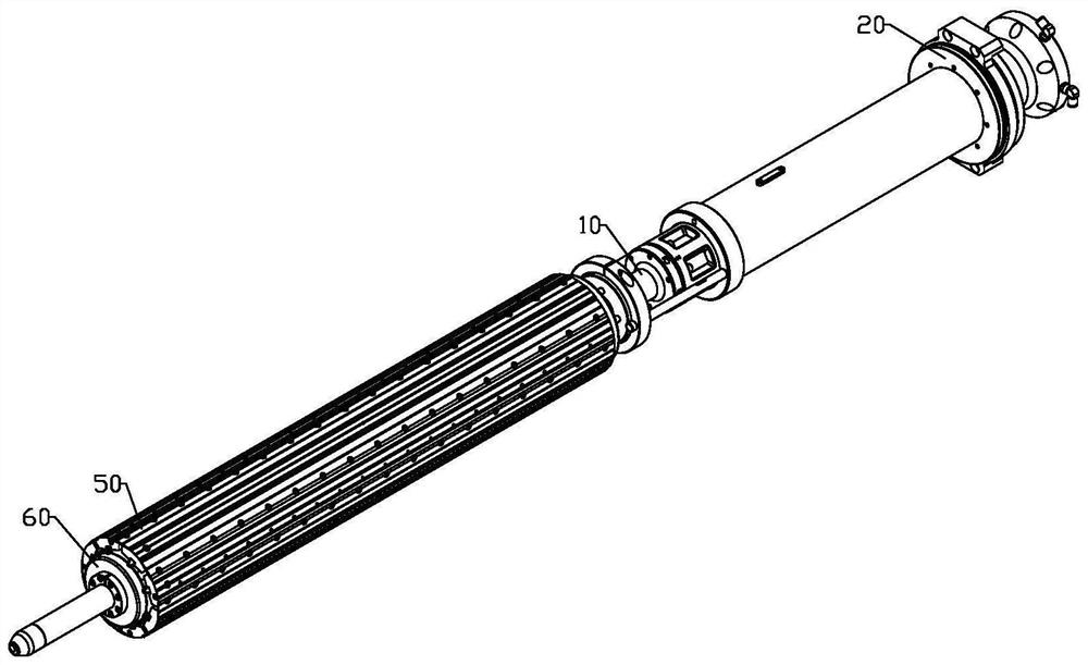
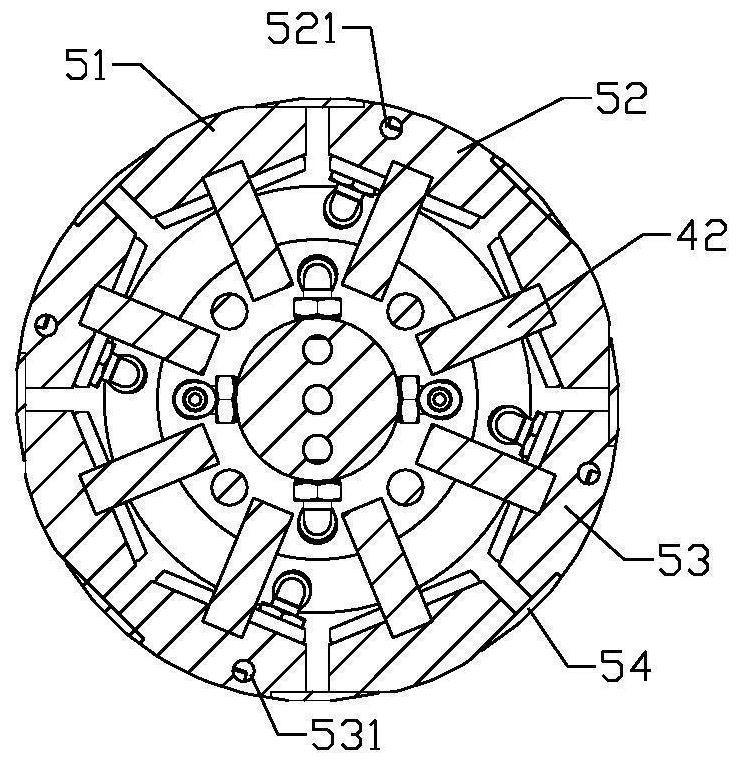
The invention provides an air spring drum. The air spring drum includes: a spindle assembly; a driving assembly which is arranged on the main shaft assembly, wherein at least one part of the driving assembly can move in the axial direction of the main shaft assembly; a transmission assembly which is in driving connection with the driving assembly, so that the transmission assembly can move in the axial direction of the main shaft assembly; a supporting assembly which is in driving connection with the transmission assembly, wherein when the transmission assembly moves in the axial direction of the main shaft assembly, the transmission assembly drives the supporting assembly to move in the radial direction of the main shaft assembly; and a drum plate assembly which is arranged in the circumferential direction of the main shaft assembly, wherein the side, close to the main shaft assembly, of the drum plate assembly is connected with the supporting assembly and moves along with the supporting assembly. The problem that in the prior art, an air spring drum is poor in use performance is solved.

Description

technical field [0001] The invention relates to the field of tire production equipment, in particular to an air spring drum. Background technique [0002] The C-type air spring drum is the core component of the air spring forming machine, and its working process includes rubber adsorption, coating, rolling, bodiless and other processes. When the rubber is applied, the suction force is provided by the vacuum generator and the power is provided by the forming machine to rotate the forming drum to apply the rubber. After the application, the pressure roller of the forming machine is rolled. After rolling, the spring drum is manually removed. In the process of manual bodiless removal, the two sides are tied with ropes, blowing air to make the rubber expand and separate from the spring drum, and then the ropes are untied to quickly release the carcass from the drum. Moreover, in the existing C-type air spring drum, the spring drum is generally a cylindrical body with a fixed di...

Claims


Application Information

Patent Timeline
Patent Type & Authority Applications(China)
IPC IPC(8): B29D30/24B29D30/26
CPCB29D30/24B29D30/26
Inventor 官炳政俞一航赵军栾英刚刘超高新腾
Owner MESNAC
Learn More