Particle filling valve

A filling valve and granule technology, which is applied in packaging, bottle filling, liquid bottling, etc., can solve the problems of slow feeding speed, poor cleaning effect, small width, etc., so as to improve feeding speed, filling quality, The effect of improving filling efficiency

Pending Publication Date: 2017-08-18
江苏普华盛包装科技有限公司
View PDF4 Cites 8 Cited by
  • Summary
  • Abstract
  • Description
  • Claims
  • Application Information

AI Technical Summary

Problems solved by technology

The disadvantages of the above particle filling valve are: (1) The dynamic and static sealing structure between the upper valve seat and the lower valve seat is composed of a sealing ring, and the sealing ring is used to ensure that when the upper valve seat and the lower valve seat move relatively, the filling channel The beverage inside will not flow out from the gap between the upper valve seat and the lower valve seat. This kind of dynamic and static sealing structure has a complex structure, and it is easy to wear and tear after long-term operation, resulting in beverage leakage. There is a hygienic dead angle that keeps beverage particles inside the filling valve. , the cleaning effect is poor; (2) The central air return method is adopted during the filling process. Due to the limitation of the size of the bottle mouth, the air return port is generally only 4-6mm, and the return air port is easily blocked by beverage particles, which affects the filling process. Filling efficiency and filling quality; (3) After the air return pipe is set in the center, due to the limitation of the size of the bottle mouth, the annular filling channel for the beverage to pass through is formed between the inner wall of the tubular filling nozzle and the central air return pipe. The width is small, which leads to slow feeding speed and affects the filling efficiency

Method used


Image

  • Particle filling valve
  • Particle filling valve
  • Particle filling valve

Examples


Embodiment Construction

[0012] The present invention will be further described below in conjunction with the accompanying drawings and specific embodiments.

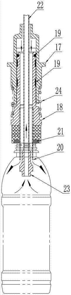
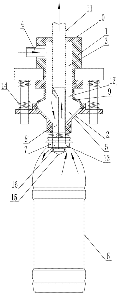
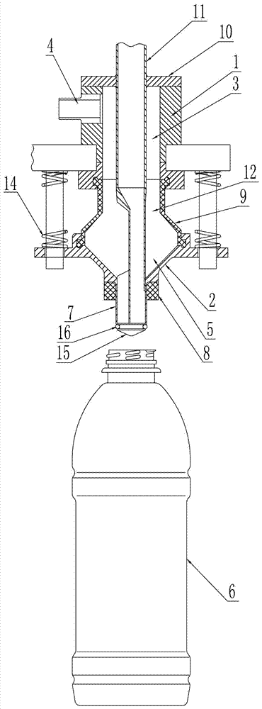
[0013] like figure 2 , image 3 As shown, the described particle filling valve includes an upper valve seat 1 and a lower valve seat 2, the upper valve seat 1 is provided with a first inner cavity 3 axially penetrating the upper valve seat 1, and the upper valve seat The side wall of 1 is provided with a feed hole 4 communicating with the first inner chamber 3, and a second inner chamber 5 axially penetrating the lower valve seat 2 is arranged in the lower valve seat 2, and the bottom of the lower valve seat 2 is downward An integral extension has a tubular filling nozzle 7 whose interior communicates with the second inner cavity 5 and can be inserted into the mouth of the bottle 6. A bottle mouth sealing ring 8 is sleeved outside the tubular filling nozzle 7. The upper valve seat 1 is connected with the lower valve seat 2 through the flexib...


PUM


Abstract

The invention discloses a particle filling valve which comprises an upper valve base and a lower valve base. Inner cavities penetrating the corresponding valve bases are formed in the upper valve base and the lower valve base correspondingly, a feeding hole is formed in the side wall of the upper valve base, a pipe-shaped filling nozzle with a bottle opening sealing ring is arranged at the bottom of the lower valve base, and the upper valve base and the lower valve base are connected through a flexible cup; a valve cap is arranged at the top of the upper valve base and is provided with an eccentric air return pipe, the upper end of the eccentric air return pipe extends out of the valve cap, the lower end of the eccentric air return pipe downwards penetrates the upper valve base, the flexible cup and the lower valve base sequentially to be tightly attached to the inner wall of the pipe-shaped filling nozzle, then downwards extend out of the pipe-shaped filling nozzle and be provided with a sealing plug, and an opening type air return opening is formed in the side wall of a pipe section, in sliding contact sealing with the pipe-shaped filling nozzle, of the eccentric air return pipe; and reset springs are arranged on the outer sides of the upper valve base and the lower valve base, and the reset spring enables the lower valve base to have the trend that the pipe-shaped filling nozzle is tightly pressed on the sealing plug all the time. The particle filling valve has the beneficial effects that sanitation dead corners are avoided, and the air return opening can be prevented from being blocked.

Description

technical field [0001] The invention relates to the technical field of beverage filling equipment, in particular to a particle filling valve. Background technique [0002] The particle filling valve is a commonly used filling valve in the beverage filling industry. It is mainly used for filling beverages with particles such as pulp. like figure 1 As shown, the structure of the currently used particle filling valve is as follows: it includes an upper valve seat 17 and a lower valve seat 18, and the upper valve seat 17 and the lower valve seat 18 are respectively provided with an inner cavity axially penetrating the corresponding valve seat, The upper end of the lower valve seat 18 moves upwards and is inserted into the inner cavity of the upper valve seat 17 so that the inner cavity of the upper valve seat 17 communicates with the inner cavity of the lower valve seat 18. The wall is provided with grooves for placing several sealing rings from top to bottom, and sealing ring...

Claims


Application Information

Patent Timeline
Patent Type & Authority Applications(China)
IPC IPC(8): B67C3/24B67C3/26
CPCB67C3/24B67C3/2637B67C2003/2602
Inventor 黄宏伟钱擎天
Owner 江苏普华盛包装科技有限公司
Why Eureka
Try Eureka