Vapor Recovery System for Steam Wax Remover

A technology of recovery system and wax removal vehicle, which is applied in the direction of cleaning equipment, wellbore/well components, isolation devices, etc., can solve the problems of wasting steam, large energy waste, and low efficiency, and achieve the effect of reducing waste and improving the effect

Active Publication Date: 2019-04-23
克拉玛依众城石油装备研究院股份有限公司 +1
View PDF8 Cites 0 Cited by
  • Summary
  • Abstract
  • Description
  • Claims
  • Application Information

AI Technical Summary

Problems solved by technology

[0003] The technical problem to be solved by the present invention is that a large amount of steam needs to be wasted during the washing process of the steam car, which leads to a large waste of energy and relatively low efficiency. At the same time, the steam or liquefied liquid is recovered to avoid excessive waste of energy

Method used


Image

  • Vapor Recovery System for Steam Wax Remover
  • Vapor Recovery System for Steam Wax Remover

Examples


Embodiment

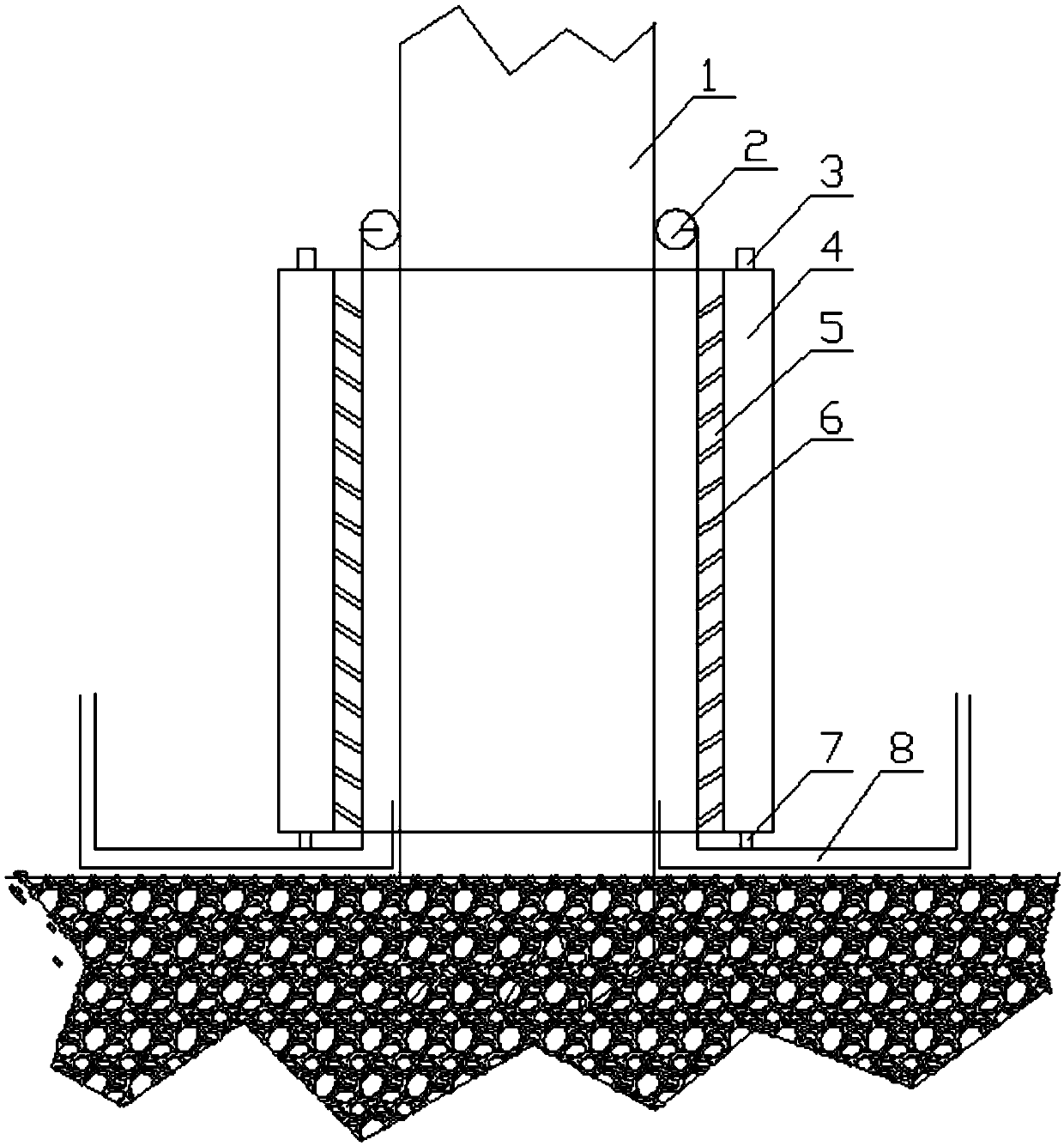
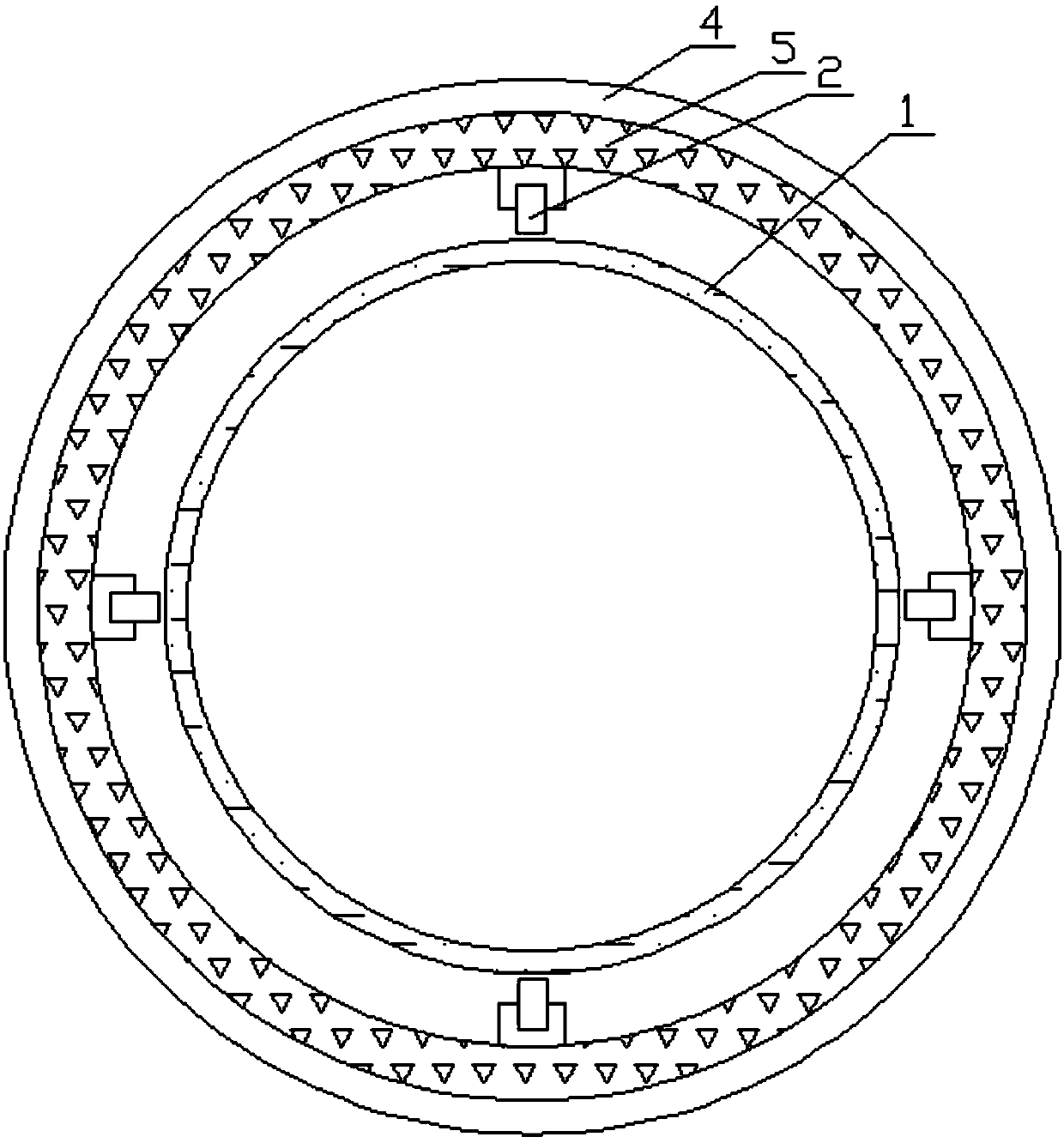
[0021] Such as figure 1 and figure 2 As shown, the steam recovery system of the steam wax removal vehicle includes an oil suction pipe 1, and also includes a casing and a steam insulation layer 5, both of which are cylinders, and the steam insulation layer 5 is placed inside the casing, A cavity 4 is formed between the shell and the steam isolation layer 5, and the cavity 4 is sealed up and down; the upper surface of the cavity 4 is provided with a plurality of steam inlets 3; the wall of the steam isolation layer 5 is uniformly provided with A plurality of steam injection holes 6; there is a gap between the inner side of the steam isolation layer 5 and the oil suction pipe 1, and a steam recovery pipe 8 on the wall of the oil suction pipe is arranged at the bottom of the gap.

[0022] The central axis of the steam injection hole 6 inside the steam isolation layer 5 is higher than the central axis of the steam injection hole 6 outside the steam isolation layer 5; the angle r...


PUM


Abstract

The invention discloses a steam recycling system for a steam dewaxing vehicle. The system comprises an oil pumping pipe, an outer shell and a steam isolating layer. The outer shell and steam isolating layer are cylindrical. The steam isolating layer is arranged on the inner side of the outer shell. A cavity is formed between the outer shell and the steam isolating layer. The upper portion and lower portion of the cavity are sealed. A plurality of steam inlets are formed in the surface of the cavity. A plurality of steam injection holes are formed evenly in the wall body of the steam isolating layer. Gaps are formed between the inner side of the steam isolating layer and the oil pumping pipe. Oil pumping pipe wall body steam recycling pipes are arranged at the bottom of the gaps. According to the steam recycling system for steam dewaxing vehicle, by arranging the oil pumping pipe wall body steam recycling pipes, liquefied liquid and non-liquefied steam are directly discharged out of a well mouth; since the recycled liquid and steam are returned back to the steam vehicle by the oil pumping pipe wall body steam recycling pipes, and waste of steam is reduced.

Description

technical field [0001] The invention relates to the field of petroleum equipment, in particular to a steam recovery system for a steam wax removal vehicle. Background technique [0002] At present, the main method of wax removal in oil fields is on-site wax removal by steam truck. Because of the high-temperature steam operation during the cleaning process, the steam truck needs to waste a lot of steam during the washing process, which leads to a large waste of energy and low efficiency. Contents of the invention [0003] The technical problem to be solved by the present invention is that a large amount of steam needs to be wasted in the washing process of the steam car, which leads to a large waste of energy and relatively low efficiency. At the same time, the steam or liquefied liquid is recovered to avoid excessive waste of energy. [0004] The present invention realizes through following technical scheme: [0005] The steam recovery system of the steam wax removal veh...

Claims


Application Information

Patent Timeline
Patent Type & Authority Patents(China)
IPC IPC(8): E21B37/00E21B36/00
CPCE21B36/005E21B37/00
Inventor 柳青陈龙曾丽娟谢璞蔓
Owner 克拉玛依众城石油装备研究院股份有限公司
Why Eureka
Try Eureka