
Hydraulic control loop of mechanical arm and action method

A hydraulic circuit and control circuit technology, which is applied in the direction of mechanical equipment, fluid pressure actuation device, fluid pressure actuation system safety, etc., can solve the problems of unstable descending speed and safety performance to be improved, so as to simplify the circuit and prevent overspeed Instability, the effect of small system power loss

Active Publication Date: 2017-08-18
SHANDONG JIANZHU UNIV
View PDF12 Cites 14 Cited by
  • Summary
  • Abstract
  • Description
  • Claims
  • Application Information

AI Technical Summary

Problems solved by technology

[0004] The application publication number is CN105332959A for a hydraulic control circuit of a handling manipulator. Its lifting hydraulic control circuit is not involved in overcoming the instability of the descending speed, and its safety performance needs to be improved.

Method used


Image

  • Hydraulic control loop of mechanical arm and action method

Examples


Embodiment Construction

[0025] In order to make the technical problems, technical solutions and advantages to be solved by the present invention clearer, the following will describe in detail with reference to the drawings and specific embodiments.

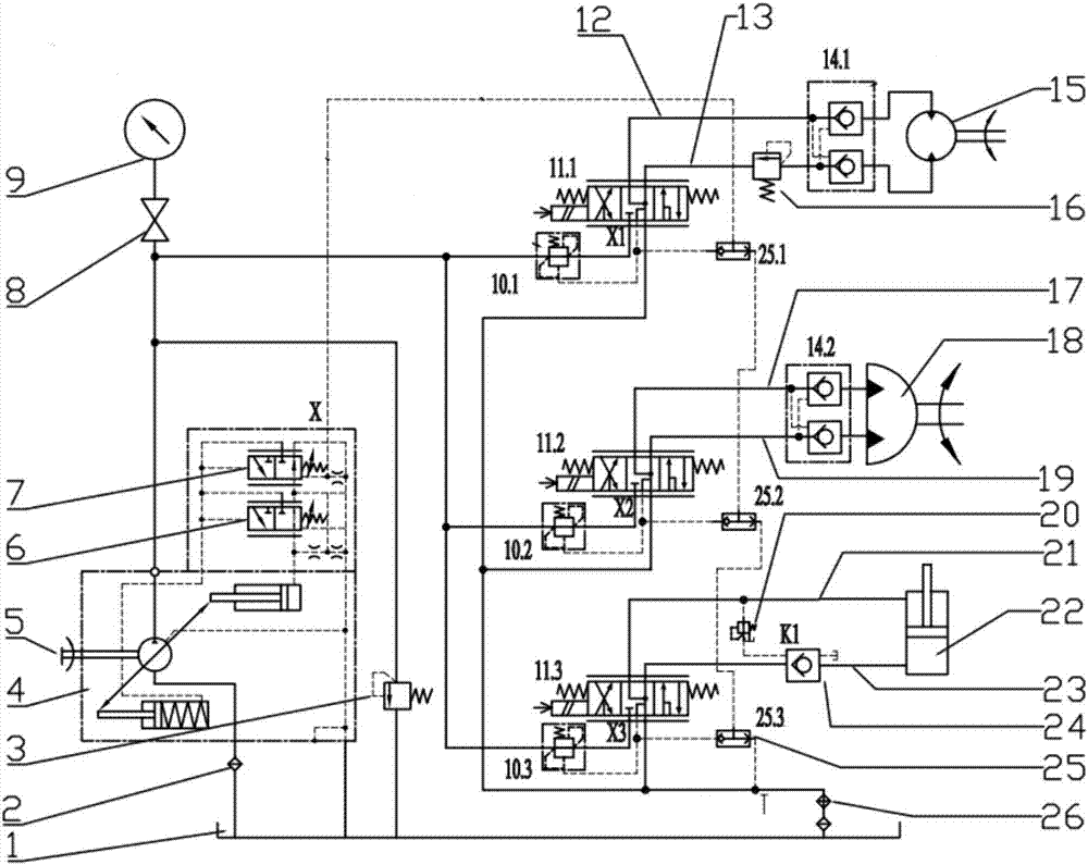
[0026] On the one hand, the present invention provides a mechanical arm hydraulic control circuit, such as figure 1 As shown, including the overall hydraulic circuit, lifting hydraulic circuit, swing hydraulic circuit and swing hydraulic circuit, where:

[0027] The overall hydraulic circuit includes oil tank 1, oil filter 2, motor 5, load sensing pump 4, shuttle valve group 25, safety valve 3, pressure gauge 9, pressure gauge switch 8 and cooler 26, oil tank 1 is connected to The oil inlet port of the load sensing pump 4 is connected, and the oil outlet port of the load sensing pump 4 is connected to the oil tank 1 through the safety valve 3, and the hydraulic oil is pumped out from the oil tank 1 through the oil filter 2 by the load sensing pump 4, and...


PUM


Abstract

The invention discloses a hydraulic control loop of a mechanical arm and an action method, and belongs to the field of hydraulic loop control over the mechanical arms. The hydraulic control loop of the mechanical arm comprises a general hydraulic loop, a lifting hydraulic loop, a rotary hydraulic loop and a swinging hydraulic loop, wherein the general hydraulic loop comprises an oil tank, an oil filter, a motor, a load sensitive pump, a shuttle valve group, a safety valve, a pressure meter, a pressure meter switch and a cooler; the oil tank is connected with an oil inlet of the load sensitive pump through the oil filter; an oil outlet of the load sensitive pump is connected with the oil tank through the safety valve; hydraulic oil is pumped out of the oil tank through the load sensitive pump via the oil filter; and one path of the hydraulic oil is connected with the pressure meter and the pressure meter switch, and the other path of the hydraulic oil is connected with the lifting hydraulic loop, the rotary hydraulic loop and the swinging hydraulic loop respectively through a main oil pipe and finally is connected with the oil tank through the cooler and the oil filter. The hydraulic control loop of the mechanical arm is safe and low in system power loss and can meet the self-locking property of a hydraulic arm and prevent overspeed instability of an oil cylinder during retraction.

Description

technical field [0001] The invention relates to the field of hydraulic circuit control of a mechanical arm, in particular to a hydraulic control circuit and an action method of a mechanical arm. Background technique [0002] The robotic arm is an industrial operating device that imitates the human arm. The robotic arm can grab and carry objects or operate tools according to a fixed program through the front gripper or other devices. It can replace the heavy and repetitive labor of humans to realize the mechanization of production. And automation, can operate in a harmful environment to protect personal safety, so it is widely used in machinery manufacturing, metallurgy, electronics, light industry and atomic energy and other departments. The hydraulic system is the core control system of the hydraulic circuit of the manipulator, which directly determines the action performance of the whole manipulator. Designers mainly consider the function and production cost of the hydrau...

Claims


Application Information

Patent Timeline
Patent Type & Authority Applications(China)
IPC IPC(8): F15B11/08F15B13/02F15B20/00
CPCF15B11/08F15B13/02F15B20/00
Inventor 鲁守银李艳萍隋首钢王涛王庆伟杨锋刘力强
Owner SHANDONG JIANZHU UNIV
Learn More