Core pulling rivet with internally-arranged lock ring

A technology of blind rivets and lock rings, which is applied to rivets, screws, threaded fasteners, etc., which can solve the problems of easy fall off of lock rings and failure of lock ring installation, and achieve the effect of simple accessories, improved reliability and fewer parts

Inactive Publication Date: 2017-08-18
AEROSPACE PRECISION PROD INC LTD
View PDF7 Cites 8 Cited by
  • Summary
  • Abstract
  • Description
  • Claims
  • Application Information

AI Technical Summary

Problems solved by technology

However, when these blind rivets are installed, the lock ring has the risk of installation failure, and the lock ring is relatively easy to fall off

Method used


Image

  • Core pulling rivet with internally-arranged lock ring
  • Core pulling rivet with internally-arranged lock ring
  • Core pulling rivet with internally-arranged lock ring

Examples


Embodiment Construction

[0024] The present invention will be described in detail below with reference to the accompanying drawings.

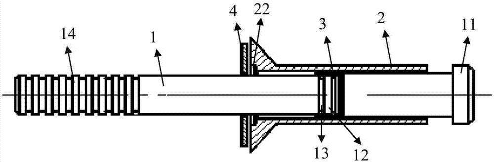
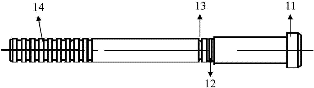
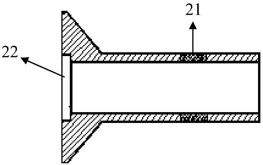
[0025] The structure created by the present invention is as figure 1 As shown, it includes a mandrel 1, a nail sleeve 2, a lock ring 3 and an anvil 4; The lock ring groove 12, the tail is provided with a clamping section 14; the lock ring groove 12 is located between the limiting platform 11 and the broken neck groove 13; the nail sleeve 2 is set on the core rod 1, The tail of the nail sleeve 2 can be limited by the limit platform 11 of the core rod 1, the length of the nail sleeve 2 is greater than the length of the distance between the step surface of the limit platform 11 and the broken neck groove 13, The nail sleeve 2 is provided with a section of deformable section 21. When the nail sleeve 2 is in the limiting position limited by the limiting platform 11, the deformable section 21 is located between the limiting platform 11 and the lock ring groove 12. between;...


PUM


Abstract

The invention provides a core pulling rivet. The core pulling rivet comprises a core rod, a rivet sleeve, a lock ring and an anvil piece. A limiting table is arranged on the head of the core rod, a broken neck groove and a lock ring groove used for containing the lock ring are formed in the middle of the core rod, and a clamping segment is arranged at the tail of the core rod. The lock ring groove is located between the limiting table and the broken neck groove. The rivet sleeve is mounted on the core rod in a sleeving manner. The tail of the rivet sleeve can be limited by the limiting table of the core rod. The length of the rivet sleeve is larger than the length of the distance between the step face of the limiting table and the broken neck groove. A deformable segment is arranged on the rivet sleeve. The lock ring is made of a material capable of achieving plastic deformation. The anvil piece is mounted on the core rod in a sleeving manner and is provided with a face overlapping with the rivet sleeve and the lock ring in the direction perpendicular to the axial direction. The core pulling rivet can solve the problems that lock ring mounting is prone to failing, and falling off is prone to happening.

Description

technical field [0001] The invention relates to the field of fasteners, in particular to a bulging blind rivet with a built-in lock ring. Background technique [0002] Blind rivets are fasteners that can be installed on one side and are widely used in the connection of aerospace vehicles. Blind rivets can be used for the connection of metal materials, and there are also blind rivets specially designed for the connection of composite materials, which can withstand large tensile and shear forces. Blind rivets are widely used in single-sided installation, maintenance and other occasions. General aerospace blind rivets are composed of mandrel, nail sleeve and lock ring and other accessory parts. After the mandrel and nail sleeve are installed and riveted in place, the locking is completed by pushing the external lock ring into the locking groove. However, when these blind rivets are installed, the lock rings have the risk of installation failure, and the lock rings are relative...

Claims


Application Information

Patent Timeline
Patent Type & Authority Applications(China)
IPC IPC(8): F16B19/10
CPCF16B19/1027
Inventor 郗建豪甘美贾晓娇齐跃桂林景张晓玲郭双双
Owner AEROSPACE PRECISION PROD INC LTD
Why Eureka
Try Eureka