
Camera lens support

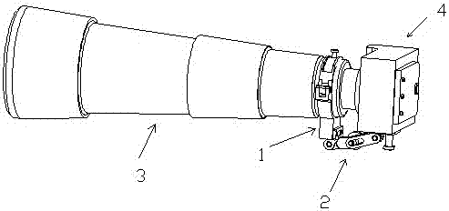
A lens holder and camera technology, applied in the field of camera accessories, can solve the problems of easy damage to the bayonet, unstable rotation, and increasing the force on the bayonet at the junction of the lens and the camera body.

Inactive Publication Date: 2017-08-18
魏志凌
View PDF0 Cites 8 Cited by
  • Summary
  • Abstract
  • Description
  • Claims
  • Application Information

AI Technical Summary

Problems solved by technology

Usually, professional photographers will add a long telescopic lens to the camera or video camera body in pursuit of clearer quality photos after shooting, or to capture animations of people and animals. For the stability of shooting, photography The teacher will prepare a tripod to support the lens. When shooting, the lens is placed on the clamping seat of the tripod head. However, the camera body and the lens itself are heavy. The unsupported camera body will increase the size of the lens and camera due to its own weight. In the long run, the bayonet at the joint is easily damaged, and in severe cases, it will cause damage to the camera body or lens
[0003] Another situation is that the tripod head is equipped with a fuselage fixing seat for the camera body to be locked and placed, but in this case the camera and lens cannot be rotated arbitrarily, and can only be rotated through the spherical joint of the tripod. Rotation is unstable, it is easy to cause blurred pictures, which seriously affects the photographer's requirements for multi-angle shooting and dynamic shooting of the scene, thereby reducing the photographer's shooting quality and shooting mood, which is an intolerable problem in the field of photography defect

Method used


Image

  • Camera lens support
  • Camera lens support
  • Camera lens support

Examples


Embodiment Construction

[0027] Embodiments of the present invention are described in detail below, examples of which are shown in the drawings, wherein the same or similar reference numerals designate the same or similar elements or elements having the same or similar functions throughout. The embodiments described below by referring to the figures are exemplary only for explaining the present invention and should not be construed as limiting the present invention.

[0028] In describing the present invention, it should be understood that the terms "upper", "lower", "bottom", "top", "front", "rear", "inner", "outer", "horizontal", " The orientation or positional relationship indicated by "vertical", etc. is based on the orientation or positional relationship shown in the drawings, which is only for the convenience of describing the present invention and simplifying the description, rather than indicating or implying that the device or element referred to must have a specific orientation, so as to Spe...


PUM


Abstract

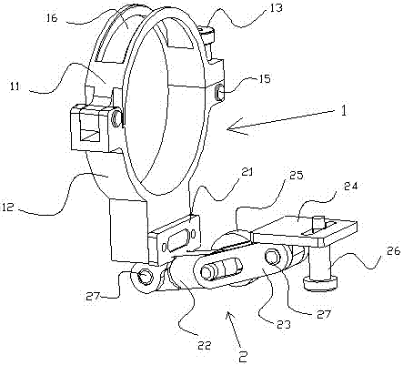
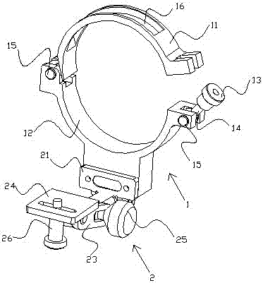
The present invention belongs to the camera accessory field and relates to a camera lens fixing support device. The support includes a lens hoop and a camera supporting frame; the lens hoop comprises an upper holding hoop and a lower holding hoop; the upper holding hoop is movably arranged at the upper end of the lower holding hoop, so that an annular structure can be formed; the lens is mounted in the annular structure and can be freely dissembled and assembled; and the camera supporting frame is fixedly arranged at the lower end of the lower holding hoop and is used for supporting and connecting the camera and adjusting the relative angular positions of the lens and the camera. The fixing support of the present invention can better protect the joint of the lens and the camera. Compared with the spherical joint rotation mode of a tripod, the support enables a photographer to stably rotate the camera and the lens according to needs so as to shoot clearer pictures and satisfies the requirements of the photographer for the dynamic capture of a scene so as to make the photographer experience the fun of photography.

Description

technical field [0001] The present application relates to the field of camera accessories, in particular to a camera lens fixing bracket device. Background technique [0002] Photography is a combination of technology and art, and the advancement of technology has provided many conveniences for countless professional photographers and photographers. Usually, professional photographers will add a long telescopic lens to the camera or camera body in pursuit of clearer quality photos after shooting, or to capture animations of people and animals. For the stability of shooting, photography The teacher will prepare a tripod to support the lens. When shooting, the lens is placed on the clamping seat of the tripod head. However, the camera body and the lens itself are heavy. The unsupported camera body will increase the size of the lens and camera due to its own weight. In the long run, the bayonet at the joint is easily damaged, and in severe cases, it will cause damage to the ca...

Claims


Application Information

Patent Timeline
Patent Type & Authority Applications(China)
IPC IPC(8): G03B17/12
CPCG03B17/12
Inventor 魏志凌
Owner 魏志凌
Learn More