Printing sleeve and method for producing a printing sleeve

A technology for printing sleeves and cylinders, which is applied in printing, printing machines, printing processes, etc., can solve the problems of consumption and cost, and achieve a good connection effect

Active Publication Date: 2017-08-18
CONTITECH ELASTOMER BESCHICHTUNGEN
View PDF7 Cites 0 Cited by
  • Summary
  • Abstract
  • Description
  • Claims
  • Application Information

AI Technical Summary

Problems solved by technology

This leads to expenditure and cost

Method used


Image

  • Printing sleeve and method for producing a printing sleeve

Examples


Embodiment Construction

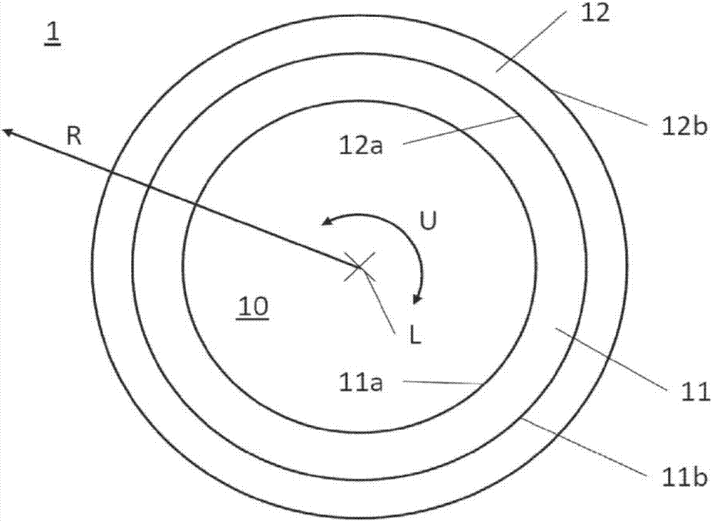
[0036] figure 1 A schematic sectional illustration of a printing sleeve 1 according to the invention is shown. The illustration shows a cross section through a printing sleeve 1 which extends cylindrically in the direction of its longitudinal axis L. FIG. The printing sleeve 1 has a first radially inner layer 11 which is formed seamlessly closed in the circumferential direction U.

[0037] The printing sleeve 1 is mounted with its first radially inner layer 11 on the printing cylinder 10 . To this end, the printing sleeve is radially expanded from the inside with compressed air. Here, the printing sleeve 1 is placed with the inner surface 11 a of the first radially inner layer 11 on the outer surface of the printing cylinder 10 with a force fit. The printing sleeve 1 also has a second radially outer layer 12 , which with its inner surface 12 a lies directly against the outer surface 11 b of the first radially inner layer 11 . The outer surface 12b of the second radially ou...


PUM


Abstract

The invention relates to a printing sleeve (1) comprising a first, radially inner layer (11) that has an inner side (11a) for making direct contact with the outer side of a printing cylinder (10), and an outer side (11b) which lies radially opposite said inner side (11a); as well as a second, radially outer layer (12) that has an outer side (12b) for forming a printing surface, and an inner side (12a) which lies radially opposite said outer side (12b). Said printing sleeve (1) is characterised in that the outer side (11b) of the first, radially inner layer (11) and the inner side (12a) of the second, radially outer layer (12) lie directly one against the other, and in that said first, radially inner layer (11) is designed to be able to absorb both forces occurring in the circumferential direction (U) and / or longitudinal direction (L), and pressures that arise in the radial direction (R).

Description

technical field [0001] The invention relates to a printing sleeve according to the preamble of claim 1 and to two methods for producing such a printing sleeve according to claims 4 and 6 . Background technique [0002] In flexographic printing, (printing) sleeves (so-called sleeves) with a dimensionally stable reinforcing carrier (so-called base sleeves) are used as printing molds, the outwardly oriented printing surfaces of these (printing) sleeves Consists of or has an elastomeric material of the type, ie, is rubber-coated. These printing dies are used on printing cylinders, which are pushed onto these cylinders with radial expansion. For this purpose, these dimensionally stable and radially difficult-to-extend printing sleeves are expanded from the inside by means of compressed air; for this purpose, these printing sleeves must be airtight. The radial stretching or expansion enables pushing onto the printing sleeve. After switching off the compressed air, the printing ...

Claims


Application Information

Patent Timeline
IPC IPC(8): B41N1/22B41F5/24
CPCB41F5/24B41N1/22B41C1/182B41C1/186
Inventor 斯特凡·菲尔格雷夫阿明·塞内延斯·勒施纳托尔斯滕·拉施多尔夫
Owner CONTITECH ELASTOMER BESCHICHTUNGEN
Why Eureka
Try Eureka