Motor vehicle lock comprising a braking pawl and a driving dog mechanism

A technology of braking claw and moving mechanism, applied in vehicle locks, building locks, application of locks, etc., can solve problems such as unavoidable opening abnormal noises

Inactive Publication Date: 2017-08-18
KIEKERT AG
View PDF7 Cites 2 Cited by
  • Summary
  • Abstract
  • Description
  • Claims
  • Application Information

AI Technical Summary

Problems solved by technology

can not avoid opening the abnormal sound

Method used


Image

  • Motor vehicle lock comprising a braking pawl and a driving dog mechanism
  • Motor vehicle lock comprising a braking pawl and a driving dog mechanism
  • Motor vehicle lock comprising a braking pawl and a driving dog mechanism

Examples


Embodiment Construction

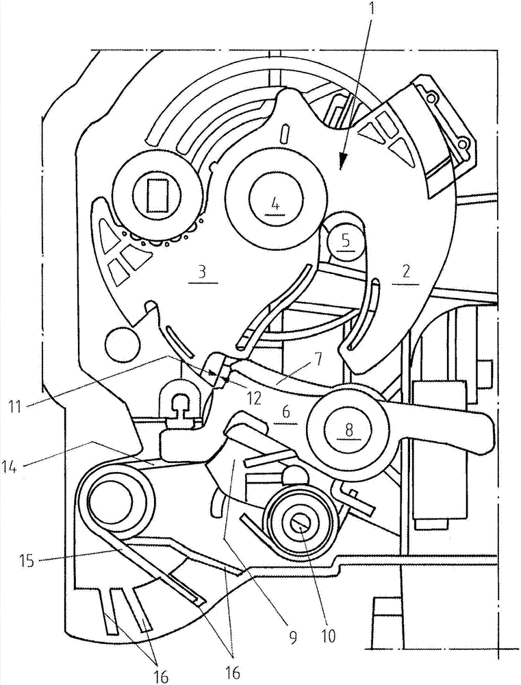
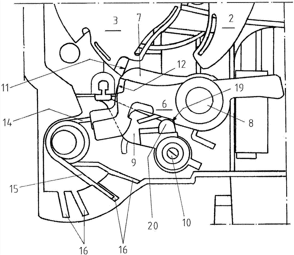
[0038] exist figure 1 A rotary latch 1 is shown, with a load arm 2 and a catch arm 3 . The rotary locking fork 1 is rotatable about its axis 4 . In the locked state, the stop 5 cannot move away from the rotary locking fork 1 . Turn lock fork 1 can be as in figure 1Locking with locking pawl 6 as shown in . Behind the locking pawl 6, a detent pawl 7 is provided. The two jaws 6 and 7 are rotatably mounted via a common shaft 8 . The lock also has a deflection lever 9 which can transmit the pivoting movement of the locking pawl 6 to the locking pawl 7 . Steering rod 9 is a driving mechanism with conversion function. The steering rod 9 is rotatably mounted via a shaft 10 .

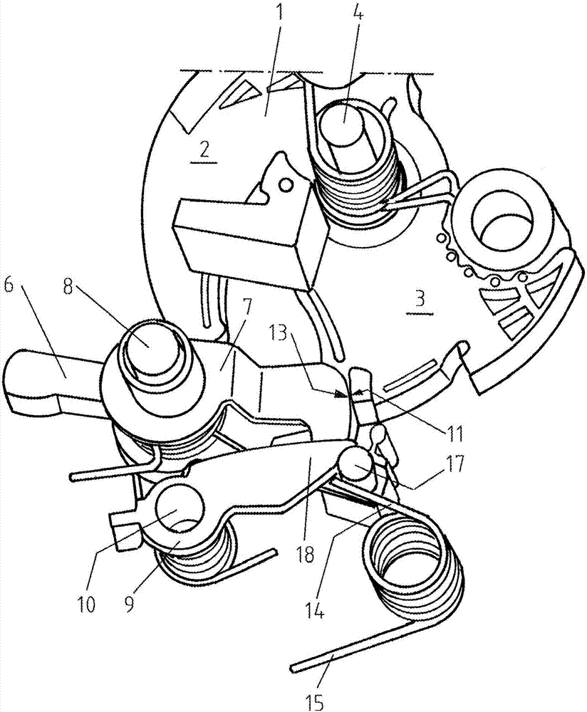
[0039] In the locked state, the locking surface 12 of the locking pawl 6 acts like figure 1 abuts against the locking surface 11 of the rotary latch 1 as shown in . Simultaneously at its rear, brake pawl 7 with braking surface 13 (seeing figure 2 ) rests against the locking surface 11 of the rotary lo...


PUM


Abstract

The aim of the invention is to provide a locking mechanism for a lock, which can be opened quietly. To achieve this aim, a lock is proposed comprising a locking mechanism with a rotary latch, a locking pawl for locking the rotary latch in a detent position and a braking pawl which initially can brake a rotary motion of the rotary latch that occurs after or during a movement of the locking pawl out of its detent position. Opening sounds can be reduced by means of this initial braking action. The lock also comprises a driving dog mechanism with a translatory action that can lift the braking pawl out of its braking position. This ensures that the braking pawl is moved out of its braking position in a reliable manner so that the lock can be opened.

Description

technical field [0001] The invention relates to a lock for a motor vehicle with a locking device and to a method for opening the locking device. Background technique [0002] The locking device comprises a rotatably mounted rotary catch for receiving the stop and a locking pawl capable of locking the rotary catch for closing. Locking device parts made of metal and / or plastic are usually mounted rotatably on a locking plate made of metal. [0003] The rotary cleat of a motor vehicle lock usually has a fork-shaped entry slot formed by the load arm and the capture arm, and when the door or hatch is closed, the stop of the door or hatch, such as the engine compartment cover or the luggage compartment cover Reach the entry slot. The stop then rotates the rotary latch from the open position into the closed position. When the rotary catch reaches the closed position, it is locked in this position by the pawl. The stop can then no longer leave the entry slot of the rotary lockin...

Claims


Application Information

Patent Timeline
Patent Type & Authority Applications(China)
IPC IPC(8): E05B77/36E05B85/26
CPCE05B77/36E05B85/26
Inventor C·富克斯P·塞德拉
Owner KIEKERT AG
Why Eureka
Try Eureka