Eureka AIR delivers breakthrough ideas for toughest innovation challenges, trusted by R&D personnel around the world.

Tower structure of vertical axis wind turbine rotor

A wind turbine, vertical axis technology, applied in the field of tower structure, can solve the problems of reduced rotor airflow efficiency, affecting rotor blade airflow, etc., and achieves the effects of increasing mechanical power, reducing on-site fabrication and installation costs, and high rigidity

Inactive Publication Date: 2019-07-23
WIND IT
View PDF6 Cites 0 Cited by
  • Summary
  • Abstract
  • Description
  • Claims
  • Application Information

AI Technical Summary

Problems solved by technology

However, the tower structure described in this document affects the air flow around the rotor blades, resulting in less efficient airflow per rotor

Method used


Image

  • Tower structure of vertical axis wind turbine rotor
  • Tower structure of vertical axis wind turbine rotor
  • Tower structure of vertical axis wind turbine rotor

Examples


Embodiment Construction

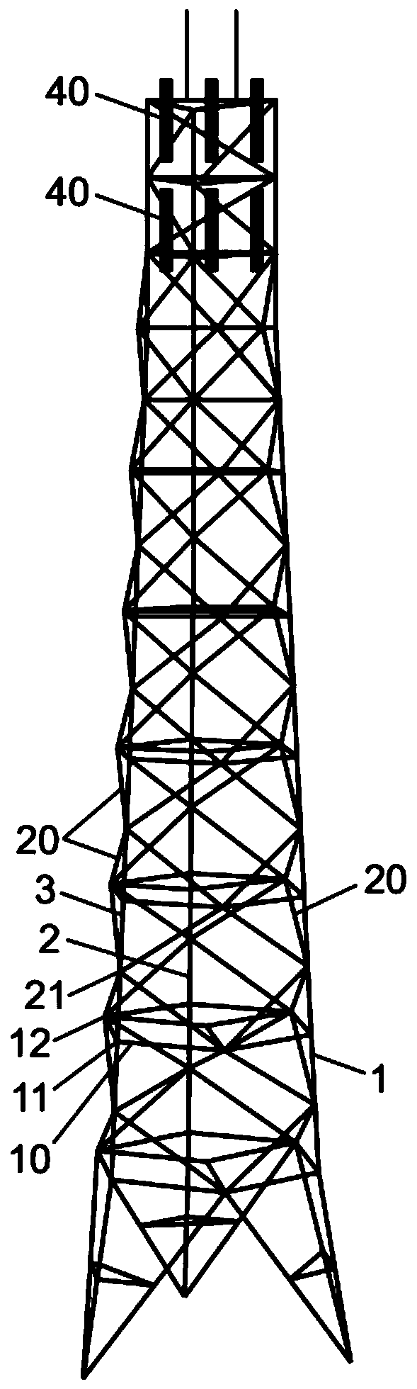
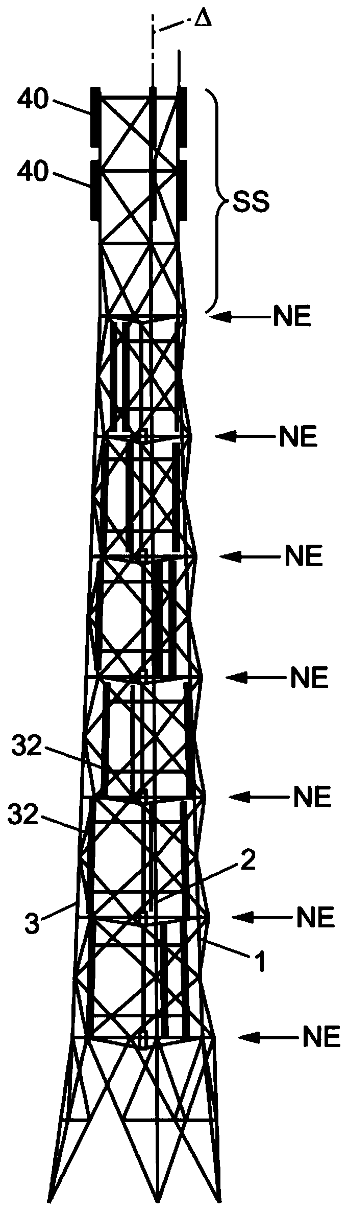
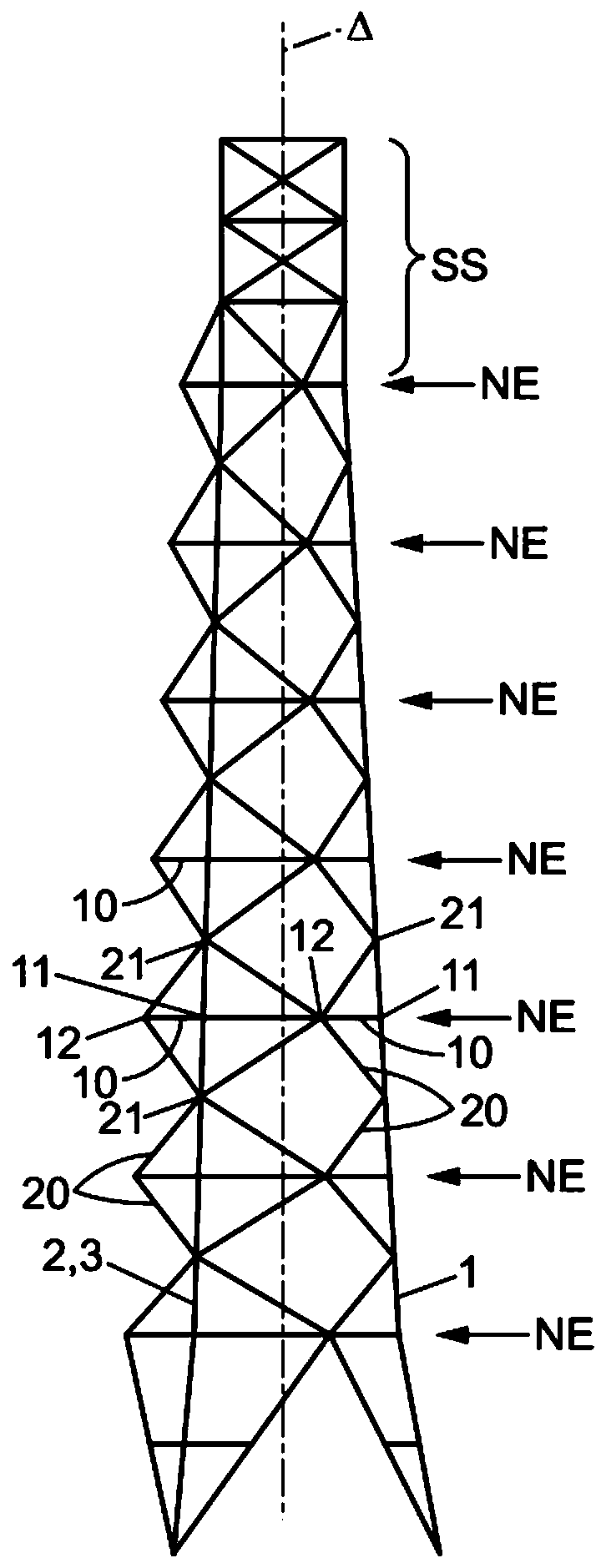
[0065] The axis Δ is vertical on the ground, and the tower structure assembly is threefold symmetric about the axis Δ. Uprights 1 to 3 are identical and each extend from the bottom of the structure to its top. The lower end of each column thus constitutes one of the three feet of the tower structure. The part of the tower structure below the lowest platform level is usually called the base or chassis, and the part between the lowest platform level and the highest platform level is usually called the running height, optionally added to the upper The structural member is called the roof.

[0066] In the first described embodiment, each column is parallel to the meridian containing the axis Δ, and the distance between the columns decreases towards the top of the structure, up to the highest platform level.

[0067] In any horizontal cross-section between the base and the top of the structure, the columns 1-3 define the vertices of an equilateral triangle.

[0068] Each platfor...


PUM


Abstract

A tower structure with multiple stacked platform levels (NE) is capable of supporting one or more vertical axis wind turbine rotors (32) such that the area swept by each rotor is enlarged to increase the mechanical power recovered by the wind turbine. Furthermore, the tower structure resists the mechanical stresses generated by the rotation of the rotors stacked to a significant height.

Description

technical field [0001] The present invention relates to a tower structure supporting one or more vertical axis wind turbine rotors. Background technique [0002] Tower structures having multiple stacked platform levels have been proposed for supporting vertical axis wind turbine rotors, the rotor being located in each platform level. For example, document FR 2,945,325 describes a hollow perforated tower structure designed to accommodate a vertical axis rotor regardless of its rotational position. However, the tower structure described in this document affects the airflow around the rotor blades, resulting in a less efficient airflow per rotor. Furthermore, said hollow structure does not necessarily maximize the performance of wind power generation, both in terms of the geometry of the tower and the composition of its structural elements. Contents of the invention [0003] In this context, the object of the invention is to improve at least some of the following criteria c...

Claims


Application Information

Patent Timeline
Patent Type & Authority Patents(China)
IPC IPC(8): F03D13/20
CPCF05B2240/9121F03D13/20F03D13/10Y02E10/728Y02E10/72
Inventor 拉斐尔·梅纳德
Owner WIND IT
Why Eureka
Eureka Blog
Learn More