Method and assistance system for recognising a fault in a system

An auxiliary system, technology for identifying equipment, applied in the field of interference and auxiliary systems for identifying equipment

Active Publication Date: 2017-08-18
SIEMENS AG
View PDF5 Cites 3 Cited by
  • Summary
  • Abstract
  • Description
  • Claims
  • Application Information

AI Technical Summary

Problems solved by technology

[0006] For example, the study of time data on the abnormal change process, that is, the time change process of the characteristic parameter, is cu

Method used


Image

  • Method and assistance system for recognising a fault in a system
  • Method and assistance system for recognising a fault in a system
  • Method and assistance system for recognising a fault in a system

Examples


Embodiment Construction

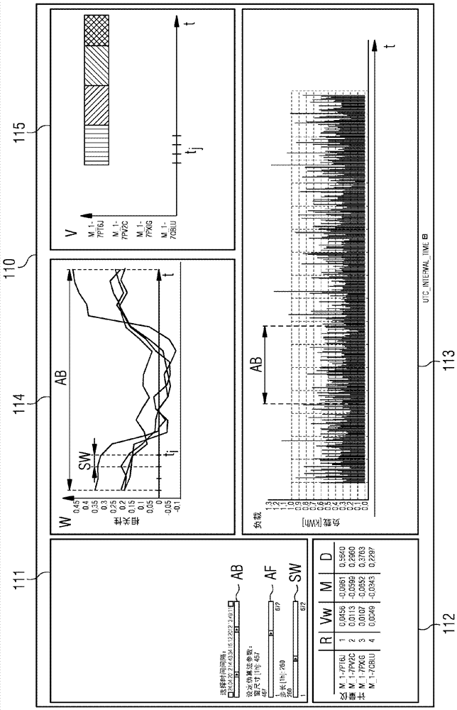
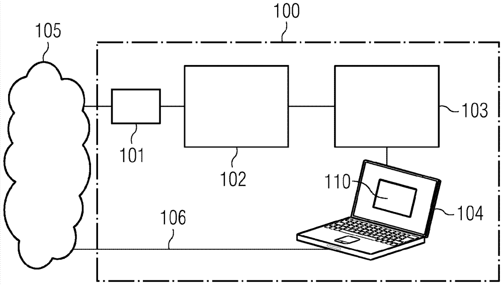
[0052] In plants such as industrial plants or manufacturing plants or also in electricity or water distribution networks, load curves over parameter values ​​such as time or pressure are recorded, for example by means of field devices or consumption meters. In order to detect disturbances or unauthorized interventions in installations or to detect unauthorized withdrawals of electricity or water in the distribution network, these load curves can be studied by auxiliary systems for anomalies in these load curves and thus determined that the resulting those parts of these load curves. These components can then be changed or the abuse eliminated.

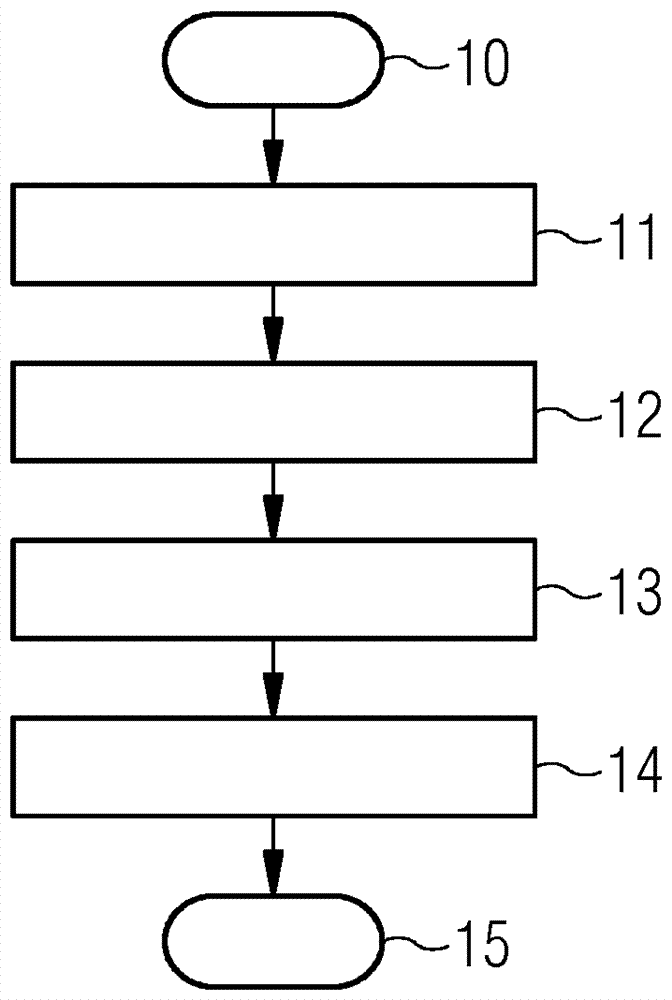
[0053] exist figure 1 The various method steps for detecting disturbances in a plant by detecting a load curve with an unusual course are schematically shown in . In the output state 10 there are several load curves, each load curve being generated by a specific component of the system. These load curves can already exist, for examp...


PUM


Abstract

The invention relates to a method for recognising a fault in a system (105) by detecting load curves with an anomalous course in a plurality of load curves, wherein a load curve represents the course of a characteristic variable over a range of values of an observed parameter of a respective component of the system (105), said method comprising the following steps: inputting (11) a plurality of load curves; providing (12) more than one group for load curves with a similar course; assigning (13) each of the input load curves to a group; determining (14) the anomalous load curves within every individual group of load curves; and releasing (15) the determined anomalous load curves and/or information relating to the determined anomalous load curves for further analysis of the fault and/or for checking the components of the system (105).

Description

technical field [0001] The invention relates to a method and an auxiliary system for identifying disturbances in a plant by detecting a load curve with an abnormal course of change from a plurality of load curves, wherein the load curves represent value ranges of parameters of individual components of the plant The change process of the above characteristic parameters. Background technique [0002] Today's manufacturing plants have a high degree of automation, in which process control and monitoring takes place, for example, by means of field devices. For this, different types of field devices are used to control different tasks, such as controlling the flow of media through input lines, controlling temperature or pressure and many others. In this case, field devices of the same type can be used for different tasks in different production steps. However, it is also possible to use, for example, different types of field devices in one production step, such as temperature se...

Claims


Application Information

Patent Timeline
IPC IPC(8): G05B23/02
CPCG05B23/0235G05B23/024
Inventor S.H.韦伯J.A.唐纳德
Owner SIEMENS AG
Why Eureka
Try Eureka