Voltage source converter and associated method

A technology of voltage source converters and converters, which is applied in the direction of output power conversion devices, electrical components, and conversion of AC power input to DC power output, and can solve problems such as slow control, high on-state loss, and high switching loss

Inactive Publication Date: 2017-08-18
ABB (SCHWEIZ) AG
View PDF6 Cites 0 Cited by
  • Summary
  • Abstract
  • Description
  • Claims
  • Application Information

AI Technical Summary

Problems solved by technology

However, LCC converters have several disadvantages: they can suffer from commutation failures, they require a strong alternating current (AC) grid, they do not support reactive power, have high harmonics, require polarity inversion for power inversion turn, leavi

Method used


Image

  • Voltage source converter and associated method
  • Voltage source converter and associated method
  • Voltage source converter and associated method

Examples


Embodiment Construction

[0036] The present invention now will be described more fully hereinafter with reference to the accompanying drawings, in which certain embodiments of the invention are shown. However, this invention may be embodied in many different forms and should not be construed as limited to the embodiments set forth herein; rather, these embodiments are provided as illustrations so that this disclosure will be thorough and complete, and will enable the present invention The scope of is fully conveyed to those skilled in the art. Like numbers refer to like elements throughout the description.

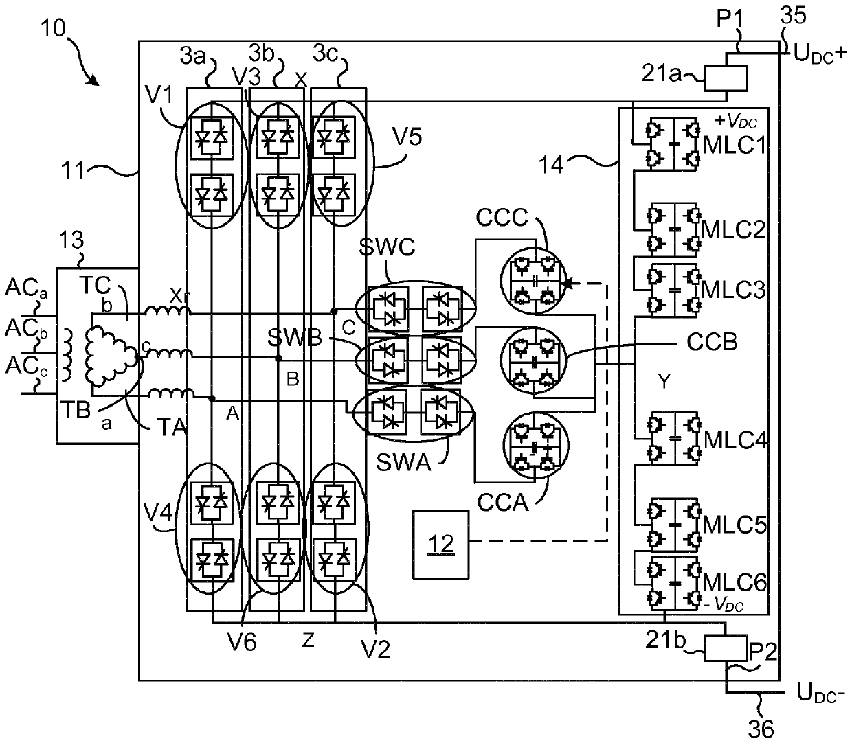
[0037] figure 1A converter 10 comprising a single converter device 11 according to a first embodiment of the invention is shown. The converter arrangement 11 comprises a three-phase bridge consisting of a first phase leg 3a, a second phase leg 3b and a third phase leg 3c. More specifically, the phase legs 3a-c are connected between a first direct current (DC) pole P1 and a second DC pole P2. T...


PUM


Abstract

It is presented a voltage source converter comprising a first converter device. The first converter device comprises: a plurality of director valves, wherein each director valve comprises two anti-parallel thyristors provided in a bridge for switching between two states, the bridge being provided in at least one phase leg connected to two a first pair of direct current poles and comprising a midpoint connected to an alternating current, AC, terminal; and at least one commutation cell connected to a respective one of the at least one phase leg, wherein the commutation cell is controllable to reverse-bias a thyristor of at least one director valve of a connected phase leg when the thyristor is to stop conducting current. By providing anti-parallel thyristors in the director valves, greater control is possible. For instance the current between the DC poles can be turned off using the director valves.

Description

technical field [0001] The present invention relates to voltage source converters and associated methods. Background technique [0002] A high voltage direct current (HVDC) converter is mainly classified into a current source converter (CSC) and a voltage source converter (VSC). CSC converters are based on line-commutated converters (LCCs) containing thyristors. Thyristors have some inherent advantages such as being rugged, having low on-state losses, being easy to connect in series with each other, having a short time overrating capability and having high power rating and low cost. Also, thyristors are well established and commonly used components. However, LCC converters have several disadvantages: they can suffer from commutation failures, they require a strong alternating current (AC) grid, they do not support reactive power, have high harmonics, require polarity inversion for power inversion turn, leaving a large coverage area, the control is slow and does not improv...

Claims


Application Information

Patent Timeline
IPC IPC(8): H02M7/19H02M7/487H02M7/49H02M7/515H02M7/525H02M1/12H02M1/15H02M1/32H02M7/162
CPCH02M1/12H02M1/15H02M1/32H02M7/1626H02M7/19H02M7/487H02M7/49H02M7/5152H02M7/525H02M1/0074H02M7/4835H02M1/0095
Inventor S.苏拉马尼安S.迈蒂
Owner ABB (SCHWEIZ) AG
Why Eureka
Try Eureka