Low power A/D converter

a converter and low power technology, applied in the field of electronic circuitry, can solve the problems of no practical use, no system use, and no system us

Inactive Publication Date: 2005-08-09
CAMERON HEALTH
View PDF68 Cites 88 Cited by
  • Summary
  • Abstract
  • Description
  • Claims
  • Application Information

AI Technical Summary

Problems solved by technology

This system is far more complicated to use than current ICD systems using transvenous lead systems together with an active can electrode and therefore it has no practical use.
It has in fact never been used because of the surgical difficulty of applying such a device (3 incisions), the impractical abdominal location of the generator and the electrically poor sensing and defibrillation aspects of such a system.
ICDs are very effective at treating V-Fib, but are therapies that still require significant surgery.
In addition, chronic transvenous lead systems, their reimplantation and removals, can damage major cardiovascular venous systems and the tricuspid valve, as well as result in life threatening perforations of the great vessels and heart.
Consequently, use of transvenous lead systems, despite their many advantages, are not without their chronic patient management limitations in those with life expectancies of >5 years.
The problem of lead complications is even greater in children where body growth can substantially alter transvenous lead function and lead to additional cardiovascular problems and revisions.
Moreover, transvenous ICD systems also increase cost and require specialized interventional rooms and equipment as well as special skill for insertion.
However, an AED must be used by another individual, not the person suffering from the potential fatal rhythm.
Because >75% of cardiac arrests occur in the home, and over half occur in the bedroom, patients at risk of cardiac arrest are often alone or asleep and can not be helped in time with an AED.
One factor which has added complexity to ICD design is the necessity to digitize an analog electrocardiogram (ECG) signal.
One problem with this approach is that each of the bus lines has a parasitic capacitance associated with them.
If one increases the number of bits of the conversion to increase resolution, additional power will be lost.
In some cases, the power loss can be worse because, if 10 bits are transferred to an 8 bit microprocessor, two transfers would be required and possibly another read / write signal line.

Method used


Image

  • Low power A/D converter
  • Low power A/D converter
  • Low power A/D converter

Examples


Embodiment Construction

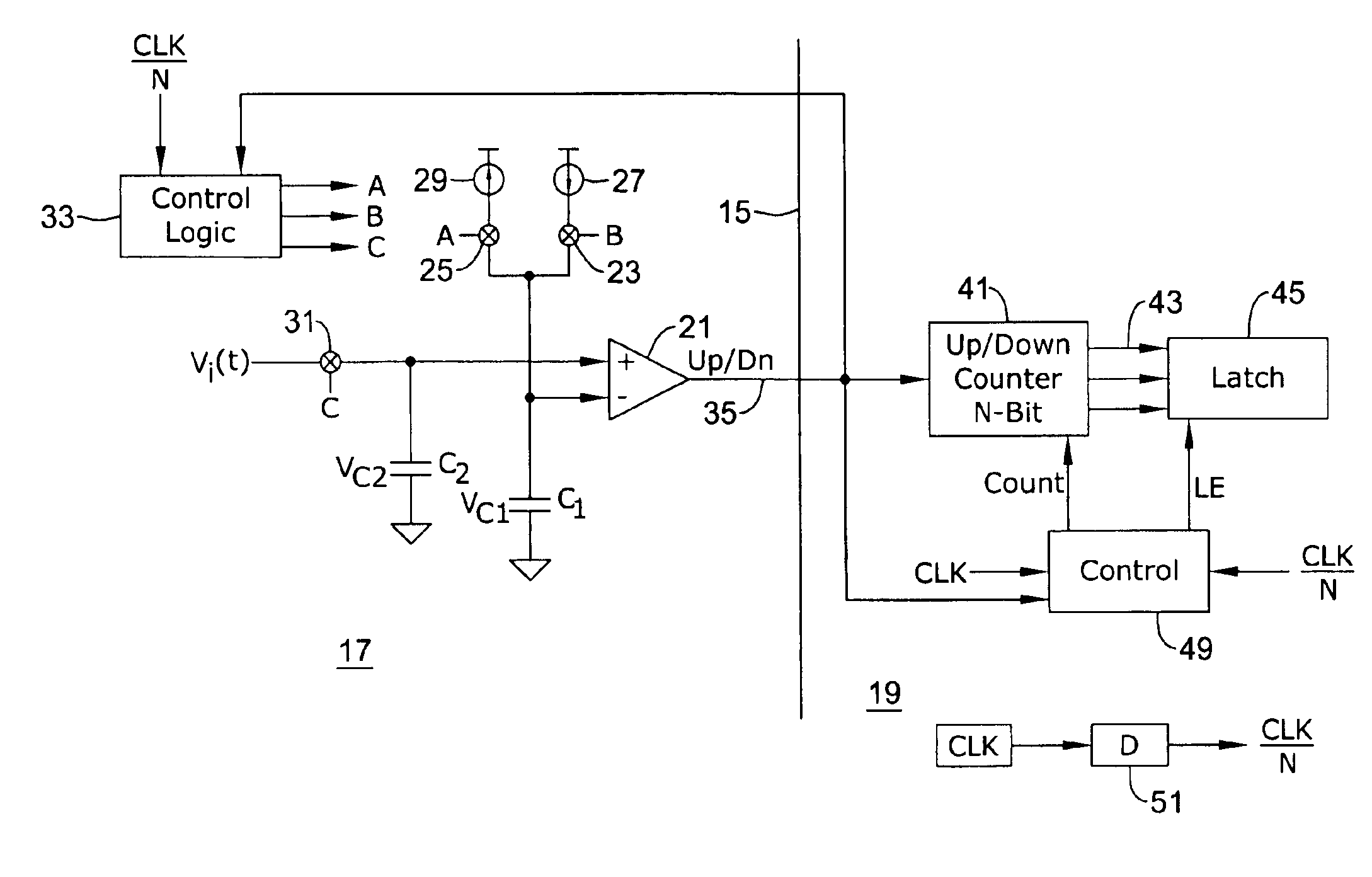
[0024]An illustrative embodiment is shown in FIG. 1, wherein the circuit is schematically divided by a line 15 into an analog side 17 and a digital side 19. The analog side 17 of the circuit includes a comparator 21 having an inverting input connected to a first terminal of a first capacitor C1 and a non-inverting input connected to the first terminal of a second capacitor C2. The second terminals of the respective capacitors C1, C2 are grounded.

[0025]The first terminal of the first capacitor C1 is arranged to be connected via operation of respective switches 23, 25 to either a first charging current source 27 or a second discharging current source 29. The switches 23, 25 are controlled by respective control signals B, A.

[0026]The second capacitor C2 is arranged to capture a sample of an analog input voltage Vi (t) which is to be converted to a digital value by the circuit. The sample is provided by momentarily closing a switch 31 in response to application of a third control signal...


PUM


Abstract

A comparator is arranged to compare a series of analog voltage signal samples on a first capacitor with a voltage on a second capacitor which is linearly increased or decreased to equal the sample value. The comparator's single output freezes the count of the counter at counts which are proportional to the voltage of the respective samples. In this manner, analog to digital conversion can be accomplished using a single line between the analog and digital sides of a circuit, thereby reducing parasitic capacitance.

Description

CROSS-REFERENCE TO RELATED APPLICATIONS[0001]The invention of the present application may find application in systems such as are disclosed in U.S. patent application entitled “SUBCUTANEOUS ONLY IMPLANTABLE CARDIOVERTER-DEFIBRILLATOR AND OPTIONAL PACER,” having U.S. Ser. No. 09 / 663,607, filed Sep. 18, 2000, pending, and U.S. patent application entitled “UNITARY SUBCUTANEOUS ONLY IMPLANTABLE CARDIOVERTER-DEFIBRILLATOR AND OPTIONAL PACER,” having U.S. Ser. No. 09 / 663,606, filed Sep. 18, 2000, pending, of which both applications are assigned to the assignee of the present application, and the disclosures of both applications are hereby incorporated by reference.[0002]In addition, the foregoing applications are related to the U.S. patent application entitled “DUCKBILL-SHAPED IMPLANTABLE CARDIOVERTER-DEFIBRILLATOR AND METHOD OF USE,” U.S. patent application entitled “CERAMICS AND / OR OTHER MATERIAL INSULATED SHELL FOR ACTIVE AND NON-ACTIVE S-ICD CAN,” U.S. patent application entitled “SUB...

Claims


Application Information

Patent Timeline
Patent Type & Authority Patents(United States)
IPC IPC(8): H03M1/50H03M1/56H03M1/48
CPCH03M1/48H03M1/56
Inventor OSTROFF, ALAN H.
Owner CAMERON HEALTH
Why Eureka
Try Eureka