LED Illumination systems

a technology of led illumination and led light, which is applied in the direction of climate sustainability, electrical equipment, and efficient power electronics conversion, etc., can solve the problems of consuming a large amount of electrical power, fluorescent light sources have a relatively short life of approximately 20,000 hours, and fluorescent light tubes are usually quite fragile, so as to improve reliability, reduce cost, and improve efficiency

Inactive Publication Date: 2011-12-22
EMD TECH
View PDF13 Cites 86 Cited by
  • Summary
  • Abstract
  • Description
  • Claims
  • Application Information

AI Technical Summary

Benefits of technology

The illumination system of this aspect has numerous advantages: There is no need to establish electrical contact or connection to any of the illumination modules, thus increased reliability, lower cost, not position dependent. The system has high efficiency (relatively low power consumption by the elimination of the ballast resistor used for LEDs in prior art systems. There is only one wire used for powering the illumination modules instead of two or four wires in the prior art illuminations systems. Quick and easy installation since there is no polarity because of using alternating current provided by the master power supply. The system can be truly waterproof when the illumination module is encapsulated since there is no connection to the outside world. This provides greater installation safety due to the absence of voltage nearby which prevents accidental contact, and since there is no touchable connection or soldering accessible.

Problems solved by technology

However, fluorescent light sources have a relatively short life of approximately 20,000 hours.
They operate at high voltage (for example, 7,000 to 15,000 volts for neon) and can consume a relatively large amount of electrical power.
Furthermore, fluorescent light tubes are usually quite fragile.
This dissipative method normally uses as much energy in the ballast resistor (i.e., dissipated energy) as in the LEDs, resulting in efficiencies sometimes even lower than 50%.
This means there is frequently a significant amount of energy wasted in heat.
However, while an increase in current increases the brightness of the light emitted by the LED, it also increases the connection temperature, which can decrease the LED's efficiency and life.
Given that LEDs are often constructed of semiconductor materials that share many comparable properties with silicone and gallium arsenide, this can be highly detrimental.
The conventional light circuits can be prone to problems other than those described above.
The LED modules joined physically using fixed electrical contact connectors, which are prone to reliability troubles.
For example, connectors can fail due to corrosion, and many devices, as well as commercial lighting systems, are used outdoors.
The LEDs have been used for illumination and in architectural and gardening designs where the robustness of the illumination system and life of the illumination system is very important since repair or replacement requires significant cost of labor (even sometimes surpassing the cost of the LED system).

Method used


Image

  • LED Illumination systems
  • LED Illumination systems
  • LED Illumination systems

Examples


Embodiment Construction

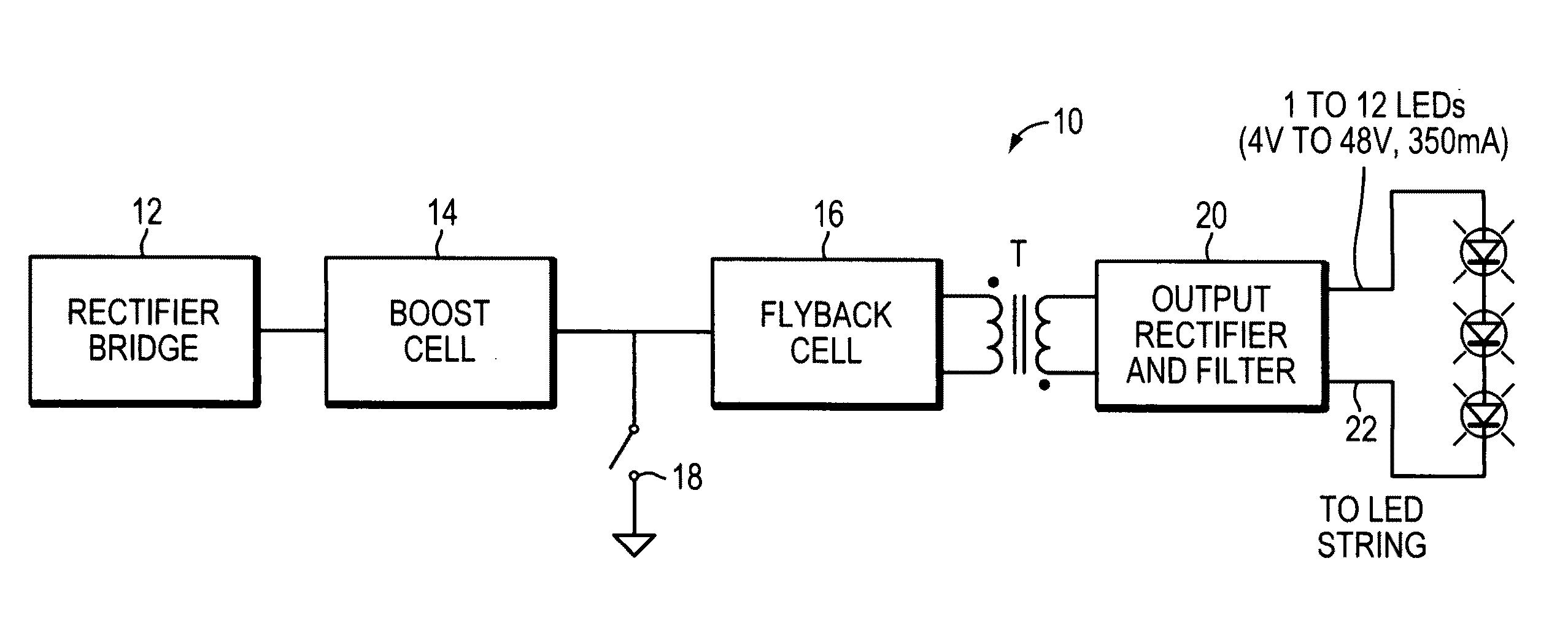
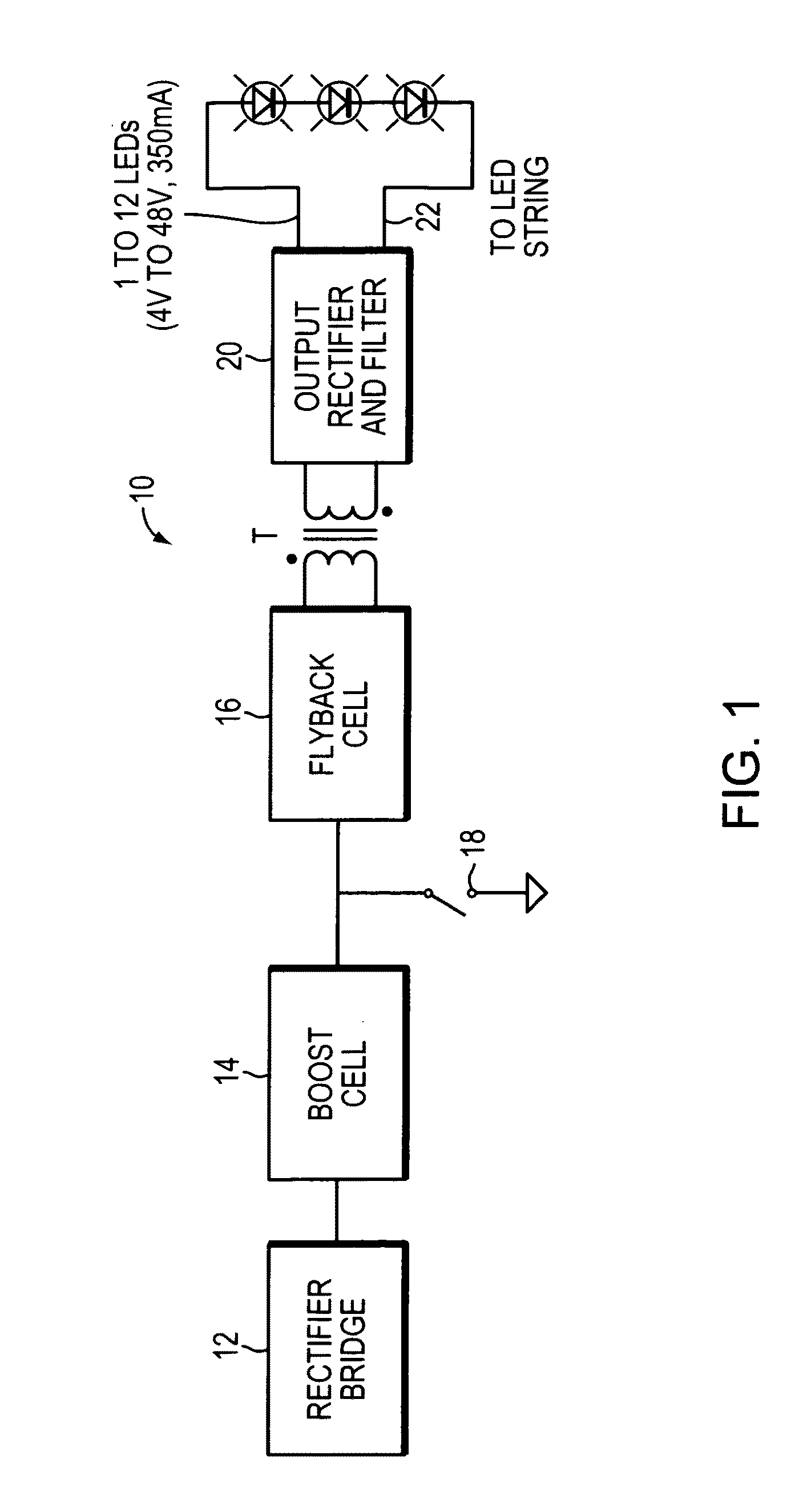
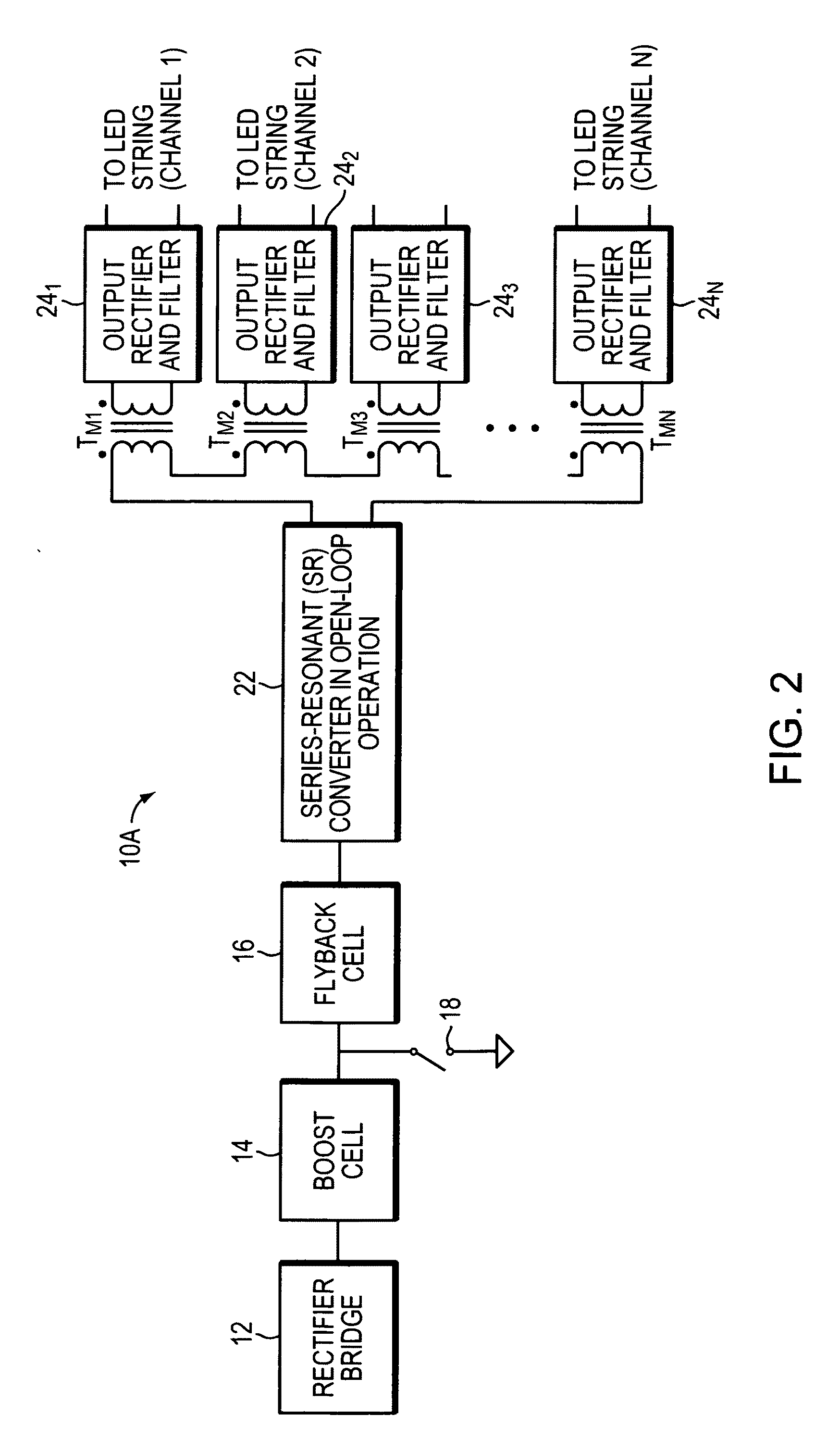
The present invention is directed to LED illumination systems and methods using novel converter power supplies. FIGS. 1, 2, 3 and 3A, illustrate diagrammatically different embodiments of converter power supplies used with LED illumination systems. Converter power supplies 10, 10A, 10B and 10C include a rectifier bridge 12, a boost cell 14 (a boost converter 14), a flyback cell 16 (a flyback converter 16), and an output rectifier and filter 20 connected to a string of light emitting diodes (LEDs). Converter power supply 10A includes, instead of a single rectifier and filter cell 20, a series of resonant converters arranged for open-loop operation 22 and connected to several rectifier and filter cells 241, 242, . . . , and 24N coupled by transformers TM1, TM2, . . . , and TMN. Each output rectifier and filter cell provides current to a string of LEDs. The rectifier and filter unit together with the string of LEDs may be packaged as an illumination module, described below. Rectifier br...


PUM


Abstract

An illumination system includes a power supply having a boost converter operating in the discontinuous conduction mode, a flyback converter operating in the critical conduction mode, and a switch coupled to the flyback converter. Several light emitting diodes receive power from the power supply. The boost converter may include a boost inductor (LB) and a boost diode (DB), constructed to perform the boost power factor correction (PFC) function. The flyback converter may includes a flyback inductor (LFB) and a flyback diode (DFB) and the power supply may be constructed to turn on the switch around the point where the current flowing in the flyback inductor reaches zero value.

Description

BACKGROUND OF THE INVENTIONThe present invention relates to illumination systems and methods using light emitting diodes (LEDs), and more particularly relates to illumination systems and methods using novel power supplies, controllers, and LED modules.Commercial lighting systems, used on the outside of commercial buildings for advertising purposes, include channel letters. Channel letters generally include a housing with a concave cross-section about 5″ deep, made of aluminum or plastic. The housing cavity, shaped as the letter, is covered by a translucent plastic sheet of a selected color, illuminated by a light source mounted within. Neon and fluorescent lights provide suitable illumination, allowing the letters to shine brightly when turned on. However, fluorescent light sources have a relatively short life of approximately 20,000 hours. They operate at high voltage (for example, 7,000 to 15,000 volts for neon) and can consume a relatively large amount of electrical power. Furthe...

Claims


Application Information

Patent Timeline
Patent Type & Authority Applications(United States)
IPC IPC(8): H05B37/02H05B44/00
CPCH02M1/4258H04B2203/5458H05B39/04Y02B70/126Y02B20/346H05B33/0815H05B45/382H05B45/38Y02B20/30Y02B70/10H05B45/385H05B39/044
Inventor BELAND, ROBERTCARLI, GIAMPAOLO
Owner EMD TECH
Why Eureka
Try Eureka