Hysteretic buck converter having dynamic thresholds

a converter and dynamic threshold technology, applied in the direction of electric variable regulation, process and machine control, instruments, etc., can solve the problems of converter power consumption, converter very inefficient during low demand conditions, converter power consumption, etc., to improve ripple control

Active Publication Date: 2009-12-31
CIRRUS LOGIC INC
View PDF99 Cites 83 Cited by
  • Summary
  • Abstract
  • Description
  • Claims
  • Application Information

AI Technical Summary

Benefits of technology

[0010]The buck switching voltage regulator circuit provides improved ripple control by anticipating the magnitude of the ripple due to load current changes. The circuit may be a control circuit active in a standby mode of a switching regulator, such as a PWM regulator that uses a PWM control mode during higher current output demand and enters standby mode during lower current output demand conditions. A comparison circuit compares the output voltage of the converter to a waveform that is generated from an ...

Problems solved by technology

At low output current levels, pulse width modulator (PWM) controllers and other types of switching power regulators that deliver high current levels under high load conditions are inefficient.
Since the pulse width becomes very narrow for low output current levels, the power used to operate the switching circuits and control/sensing circuits, which does not typically change with load current demand, predominates converter power consumption, making the converter very inefficient during low demand conditions.
Hysteretic converters have a wide dynamic range and potentially low power consumption, due to their activation only when the output voltage falls below an acceptable limit.
Also, in low power applications in which either the complexity or ...

Method used


Image

  • Hysteretic buck converter having dynamic thresholds
  • Hysteretic buck converter having dynamic thresholds
  • Hysteretic buck converter having dynamic thresholds

Examples


Embodiment Construction

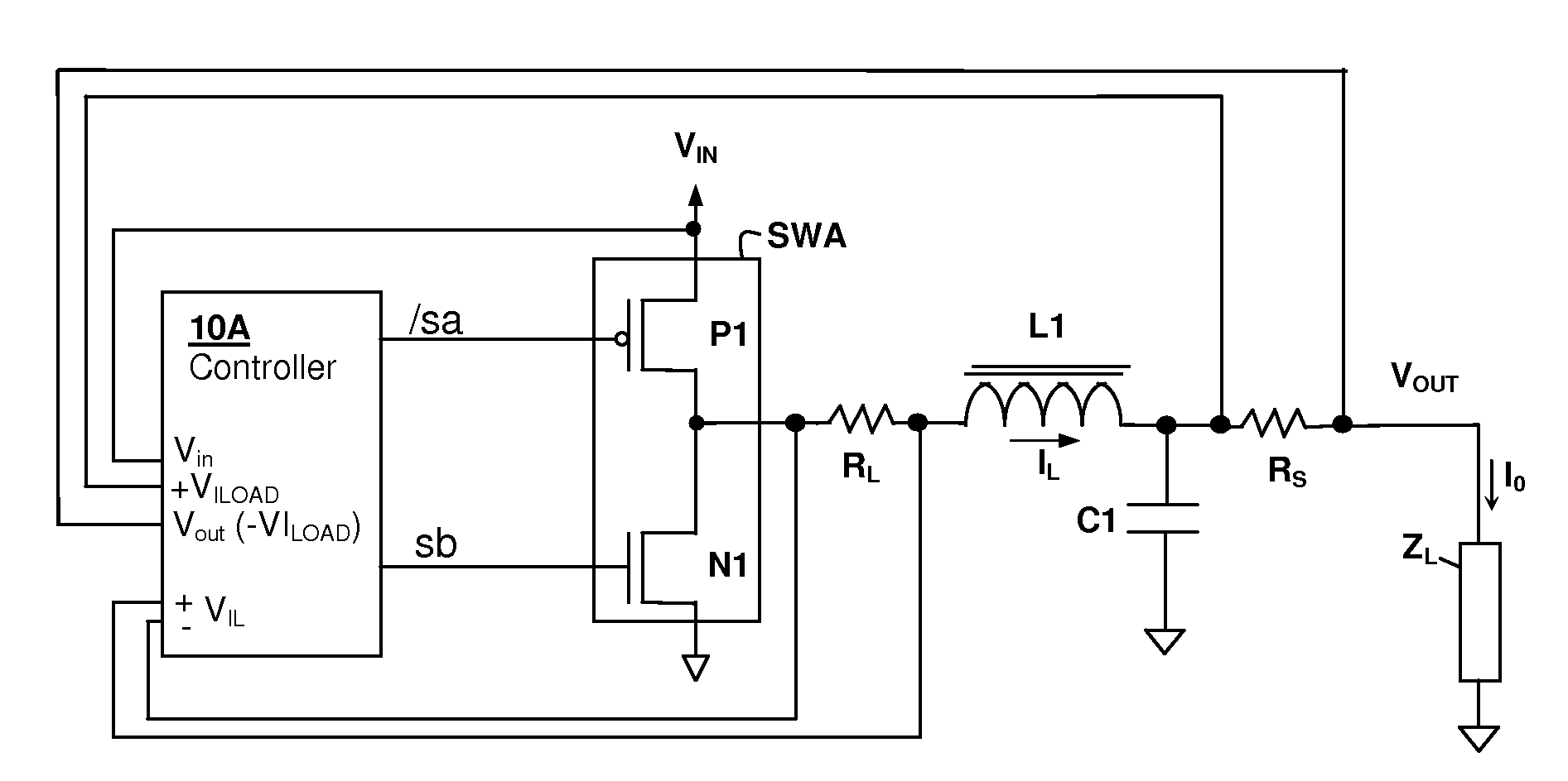
[0018]The present invention encompasses circuits and methods for providing control of a buck switching voltage regulator, in which ripple undershoot is prevented by controlling the turn-on threshold in conformity with an indication of the output current drawn by a load. The output current indication can be provided by measuring the output current directly, or as will be shown in the following description, can be calculated from the output voltage waveform and the value of the input voltage.

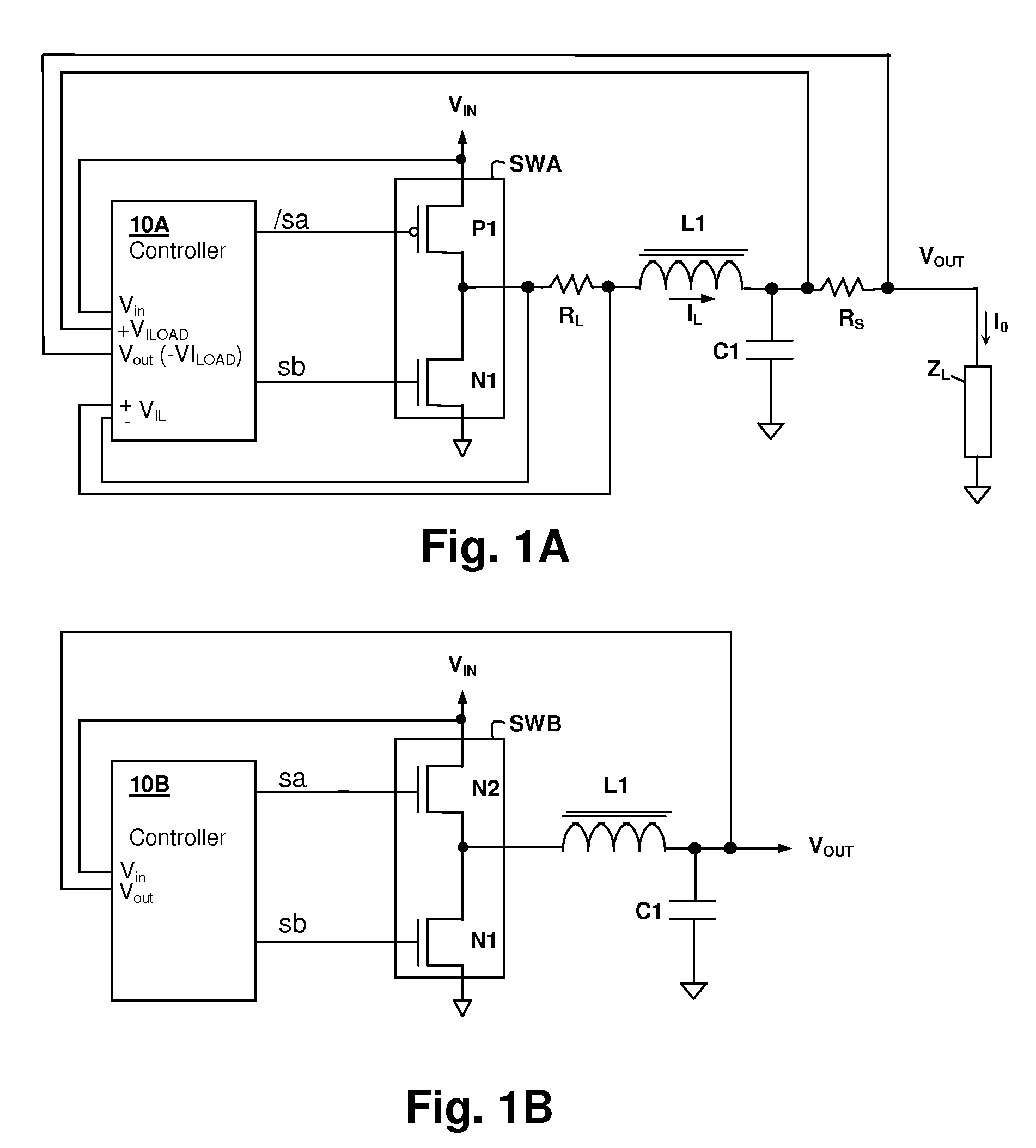
[0019]Referring now to FIG. 1A, a buck switching voltage regulator circuit in conformity with an embodiment of the invention is shown. A control circuit, controller 10A provides gate drive signals to a switching circuit SWA that couples an inductor L1 in series between an input voltage source VIN and output terminal VOUT, when transistor P1 is activated by control signal / sa. Switching circuit SWA couples inductor L1 in shunt between output terminal VOUT and a common return path (ground) associated...


PUM


Abstract

A hysteretic buck converter provides improved regulation control, in particular for buck converter standby operation. A comparison circuit compares the output voltage of the buck converter to a waveform that is generated from an indication of the output current of the converter, so that the turn-on time of the converter is advanced as the output current demand increases. The resulting action anticipates a reduction in output voltage due to the increased current, preventing an excursion of the output voltage below the ripple voltage minimum. The turn-off time of the converter is controlled by an upper threshold that limits the ripple voltage maximum. The output current indication may be a measurement of output current, or may be a dynamic value calculated from the input voltage and the output voltage waveform.

Description

BACKGROUND OF THE INVENTION[0001]1. Field of the Invention[0002]The present invention relates generally to hysteretic buck converter control schemes, and more specifically, to a buck converter control circuit in which an indication of output current is used to adjust turn-on timing dynamically.[0003]2. Background of the Invention[0004]At low output current levels, pulse width modulator (PWM) controllers and other types of switching power regulators that deliver high current levels under high load conditions are inefficient. Since the pulse width becomes very narrow for low output current levels, the power used to operate the switching circuits and control / sensing circuits, which does not typically change with load current demand, predominates converter power consumption, making the converter very inefficient during low demand conditions. Alternative controller modes are frequently implemented to operate the converter in a standby low power mode, in which the full converter dynamic p...

Claims


Application Information

Patent Timeline
IPC IPC(8): G05F1/10
CPCH02M3/1563Y02B70/16H02M2001/0032H02M2001/0019Y02B70/10H02M1/0019H02M1/0032
Inventor MELANSON, JOHN L.DING, LEI
Owner CIRRUS LOGIC INC
Why Eureka
Try Eureka