Supercharge Your Innovation With Domain-Expert AI Agents!

Voice frequency core wire disengaging device

A technology for disengaging devices and core wires, which is applied in transportation and packaging, delivery of filamentous materials, and thin material processing, etc. It can solve the problems of wasting raw materials, economic loss, core wire stuck, time loss, etc., and avoid economic losses and time loss, avoiding the effect of stuck

Inactive Publication Date: 2017-08-22
HUZHOU NANXUN RONGYE METAL MATERIAL
View PDF10 Cites 0 Cited by
  • Summary
  • Abstract
  • Description
  • Claims
  • Application Information

AI Technical Summary

Problems solved by technology

[0002] like Figure 4 As shown, the inside of the core wire coil is a mandrel with radially convex steps at both ends. There is a large hole through the middle of the mandrel, and the core wire is wound on the mandrel; the core wire coil is placed on the ground , during the process of the core wire being conveyed upward, the core wire is naturally disengaged on the core wire coil round by circle. Due to the burrs on the outer edge of the upper end of the mandrel or the notch caused by bumping during transportation, the core wire is in the process of disengagement. Jamming may occur, which may lead to two consequences: (1) The core wire is stuck, causing the core wire to break, wasting raw materials and causing economic losses, and causing time loss due to maintenance; (2) After the core wire is stuck, the The pulling force of the assembly line finally passed, but the core wire was elongated and deformed under the action of the pulling force, and the produced products were unqualified and discarded, resulting in economic losses
[0003] Therefore, the existing method of naturally releasing the core wire from the core wire reel has the disadvantages of possible stagnation, resulting in economic loss and time loss.

Method used


Image

  • Voice frequency core wire disengaging device
  • Voice frequency core wire disengaging device
  • Voice frequency core wire disengaging device

Examples


Embodiment Construction

[0017] The present invention will be further described below in conjunction with the accompanying drawings and embodiments, but not as a basis for limiting the present invention.

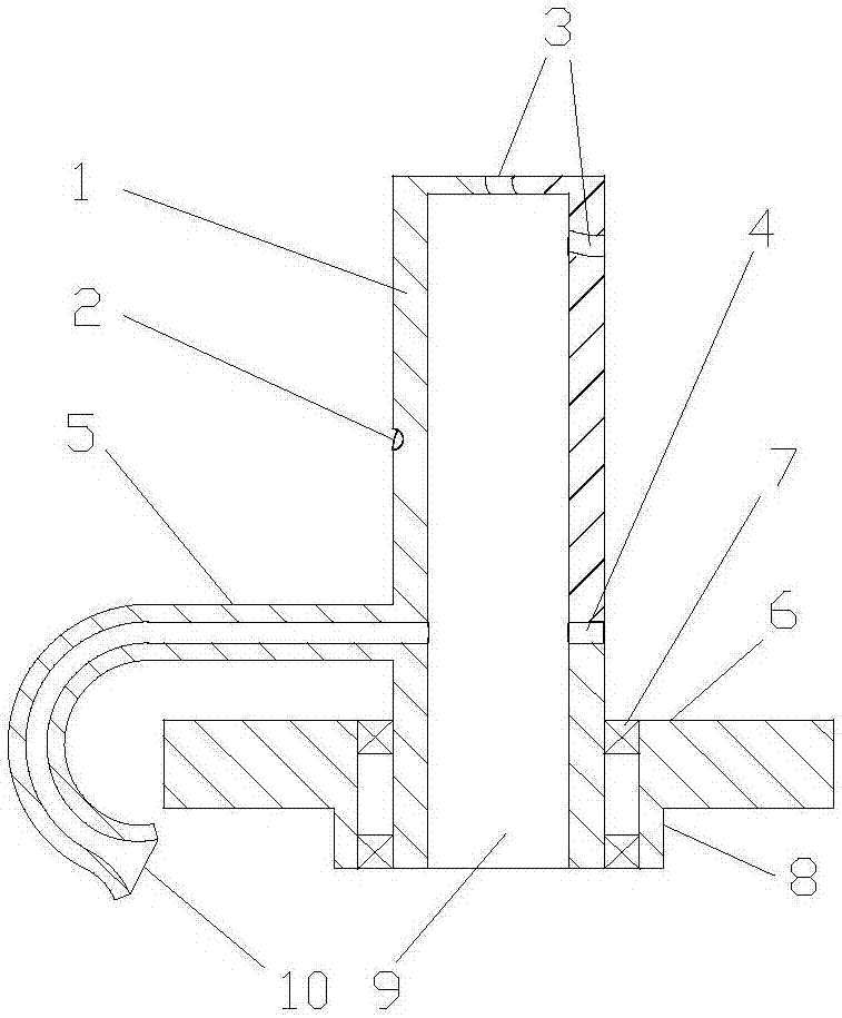
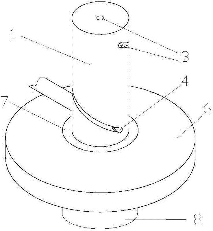
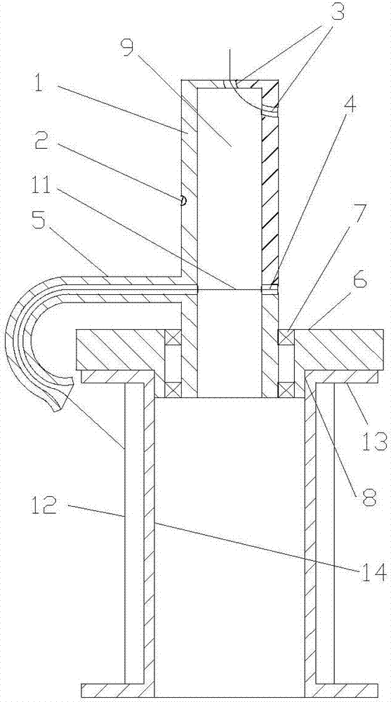
[0018] Example. An audio core wire release device, such as figure 1 and figure 2 As shown, it includes a cylindrical rotating shaft 1, a circle of coaxial helical grooves 2 is provided on the outer peripheral surface of the rotating shaft 1, and an upper through hole 3 communicating with the upper end of the groove 2 is arranged on the upper end surface of the rotating shaft 1, and the rotating shaft The side wall of the shaft 1 is provided with a lower through hole 4 that radially penetrates the shaft 1 and communicates with the lower end of the groove 2; the side wall of the shaft 1 is provided with a substantially J-shaped tubular body 5 communicating with the lower through hole 4. The J-shaped hook of the body 5 faces down and goes around the base 6. The hooked end of the tubular body 5 is p...


PUM


Abstract

The invention discloses a voice frequency core wire disengaging device which comprises a cylindrical rotating shaft (1). The outer circumferential face of the rotating shaft (1) is provided with at least one circle of spiral groove (2). The upper end face of the rotating shaft (1) is provided with upper through holes (3) communicating with the upper ends of the grooves (2). The side wall of the rotating shaft (1) is provided with a lower through hole (4) which penetrates through the rotating shaft (1) in the radial direction and communicates with the lower ends of the grooves (2). A tubular body (5) communicating with the lower through hole (4) is arranged on the side wall of the rotating shaft (1). The lower end of the rotating shaft (1) is provided with a base (6) in rotating connection with the rotating shaft (1). The rotating shaft (1) is connected to the base (6) in a rotating mode through a deep groove ball bearing (7). A boss (8) coaxial with the rotating shaft (1) is arranged below the base (6). The diameter of the boss (8) is matched with that of a large hole of a core wire coil. The voice frequency core wire disengaging device has the advantage of avoiding the phenomenon that economic losses and time losses are caused by clamping stagnation possible happening in the disengaging process of the core wire coil of core wires.

Description

technical field [0001] The invention relates to an audio core wire release device, in particular to an audio core wire release device used on an audio core wire pre-processing assembly line. Background technique [0002] Such as Figure 4 As shown, the inside of the core wire coil is a mandrel with radially convex steps at both ends. There is a large hole through the middle of the mandrel, and the core wire is wound on the mandrel; the core wire coil is placed on the ground , during the process of the core wire being conveyed upward, the core wire is naturally disengaged on the core wire coil round by circle. Due to the burrs on the outer edge of the upper end of the mandrel or the notch caused by bumping during transportation, the core wire is in the process of disengagement. Jamming may occur, which may lead to two consequences: (1) The core wire is stuck, causing the core wire to break, wasting raw materials and causing economic losses, and causing time loss due to mainte...

Claims


Application Information

Patent Timeline
IPC IPC(8): B65H75/18B65H49/18
CPCB65H49/18B65H75/18
Inventor 王建荣
Owner HUZHOU NANXUN RONGYE METAL MATERIAL
Features
  • R&D
  • Intellectual Property
  • Life Sciences
  • Materials
  • Tech Scout
  • Unparalleled Data Quality
  • Higher Quality Content
  • 60% Fewer Hallucinations
Learn More