Positioning and alarming system and method for ore pulp pipeline leakage

A pipeline leakage and alarm system technology, which is applied in the pipeline system, mechanical equipment, gas/liquid distribution and storage, etc., can solve the problems of inaccuracy, wrong judgment of the location of the leakage point, and the location of the leakage of the slurry pipeline, so as to reduce the transmission line , the effect of improving accuracy

Inactive Publication Date: 2017-08-22
YUNNAN DAHONGSHAN PIPELINE
View PDF12 Cites 14 Cited by
  • Summary
  • Abstract
  • Description
  • Claims
  • Application Information

AI Technical Summary

Problems solved by technology

[0009] The present invention aims at the problem of inaccurate leakage location in the existing slurry pipeline, and the negative pressure wave method cannot accurately determine the time difference between the upstream...

Method used


Image

  • Positioning and alarming system and method for ore pulp pipeline leakage
  • Positioning and alarming system and method for ore pulp pipeline leakage
  • Positioning and alarming system and method for ore pulp pipeline leakage

Examples


Embodiment 1

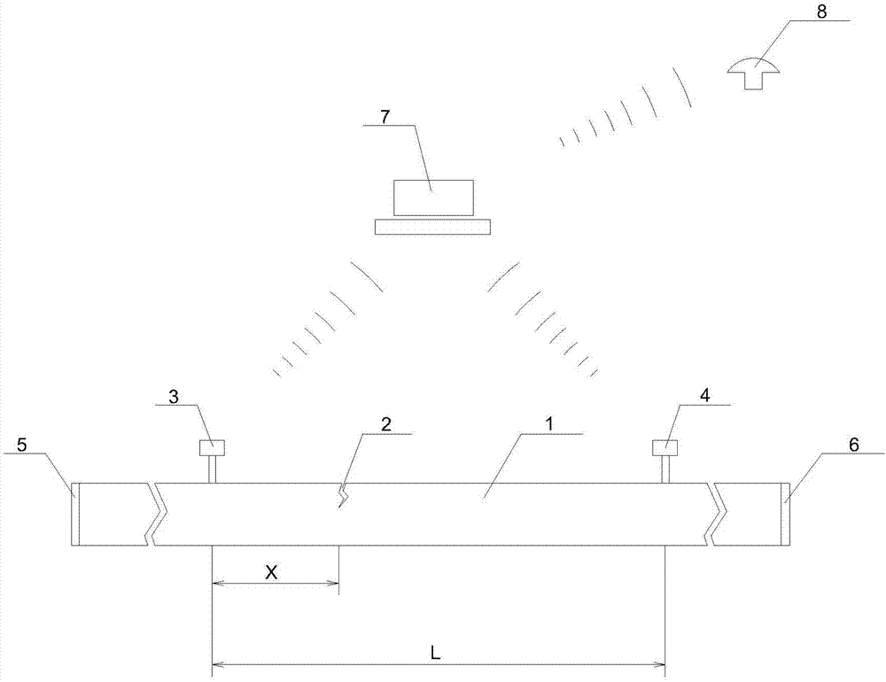
[0045] Such as figure 1 As shown, the slurry pipeline leakage location alarm system and the schematic diagram of the slurry pipeline structure, the slurry pipeline leakage location alarm system includes more than two pressure sensors, No. 1 flow sensor 5, No. 2 flow sensor 6, data processor 7 and alarm 8, two More than one pressure sensor is connected to the outer wall of the slurry pipeline 1 along the flow direction of the slurry pipeline 1, and the distance between adjacent pressure sensors is equal. The No. 1 flow sensor 5 is set at the beginning of the slurry pipeline 1, and the No. 2 flow sensor 6 is set at the end of the slurry pipeline 1. The processor 7 is respectively connected with the pressure sensor, the No. 1 flow sensor 5 , the No. 2 flow sensor 6 and the alarm 8 .

[0046] When in use, the No. 1 flow sensor, No. 2 flow sensor and pressure sensor collect statistics on the pipe pressure and pulp flow rate of the pulp pipeline during normal transportation, and obt...

Embodiment 2

[0049] Based on Embodiment 1, more than two pressure sensors, the No. 1 flow sensor 5 , the No. 2 flow sensor 6 and the alarm 8 are connected to the data processor 7 in a wireless manner.

Embodiment 3

[0051] The method for locating and alarming the leakage of the slurry pipeline comprises the following steps:

[0052] The pressure reading of the pressure sensor, the flow rate of the first flow sensor 5 and the flow rate of the second flow sensor 6 are counted by the No. 1 flow sensor 5, the No. 2 flow sensor 6 and the pressure sensor when the slurry pipeline 1 is normally transported.

[0053] The pressure wave propagation velocity a in the slurry pipeline 1 is calculated by the following formula:

[0054]

[0055] Among them, a is the pressure wave propagation velocity in the slurry pipeline 1, and the unit is m / s; K is the volume elastic coefficient of the slurry, and the unit is Pa; ρ is the average density of the slurry, and the unit is Kg / m 3 ; E is the elasticity of the slurry pipeline 1, the unit is Pa; D is the diameter of the pipeline, the unit is m; e is the thickness of the pipe wall, the unit is m; C 1 Correction factor for piping constraints.

[0056] Coll...


PUM

PropertyMeasurementUnit
Densityaaaaaaaaaa
Elastic modulusaaaaaaaaaa
Bulk modulusaaaaaaaaaa

Abstract

The invention relates to the field of ore pulp pipeline safety maintenance, in particular to a positioning and alarming system and method for ore pulp pipeline leakage. According to the technical key points of the positioning and alarming system and method, the positioning and alarming system comprises two or more pressure sensors, a first flow sensor, a second flow sensor, a datum processor and an alarming device; the two or more pressure sensors are connected with the outer wall of an ore pulp pipeline along the flow direction of the ore pulp pipeline, and the space between the adjacent pressure sensors is the same; the first flow sensor is arranged at the beginning end of the ore pulp pipeline; the second flow sensor is arranged at the tail end of the ore pulp pipeline; and the datum processor is connected with the pressure sensors, the first flow sensor, the second flow sensor and the alarming device. The negative pressure wave method and the flow balance method are combined, the problem that leakage positioning of an existing ore pulp pipeline is inaccurate is solved, and the problems that in practical application, the negative pressure wave method cannot accurately determine the time difference of an upstream pressure sensor and a downstream pressure sensor to receive the pressure wave, and thus false judging of the leakage point position is caused are solved.

Description

technical field [0001] The invention relates to the field of safety maintenance of ore pulp pipelines, in particular to a system and method for locating and alarming the leakage of ore slurry pipelines. Background technique [0002] Slurry pipelines are more and more widely used in modern society, but with the extension of pipeline operation time, pipeline leakage due to various external forces, such as earthquakes, construction, and landslides, will cause waste of resources and environmental pollution. Leakage location method, timely and accurate report of the specific geographical location of the accident pipeline, can minimize economic losses and environmental pollution. Once a leakage accident occurs in the slurry transportation pipeline, if it is not found in time, it will cause major environmental pollution and dangerous accidents. At the same time, if the leakage of the slurry is not taken in time, it will bring significant economic losses to the enterprise. Therefore...

Claims


Application Information

Patent Timeline
IPC IPC(8): F17D1/14F17D5/06
CPCF17D1/14F17D5/06
Inventor 张晓南
Owner YUNNAN DAHONGSHAN PIPELINE
Why Eureka
Try Eureka