
A novel scanning probe microscope detection method and system

A scanning probe and detection system technology, applied in the field of microscopy, can solve the problems of high cost, complex structure, unfavorable system rapid scanning imaging, etc., and achieve the effect of low cost, simple structure, and guaranteed response frequency

Active Publication Date: 2019-05-21
BEING NANO INSTR LTD
View PDF5 Cites 0 Cited by
  • Summary
  • Abstract
  • Description
  • Claims
  • Application Information

AI Technical Summary

Problems solved by technology

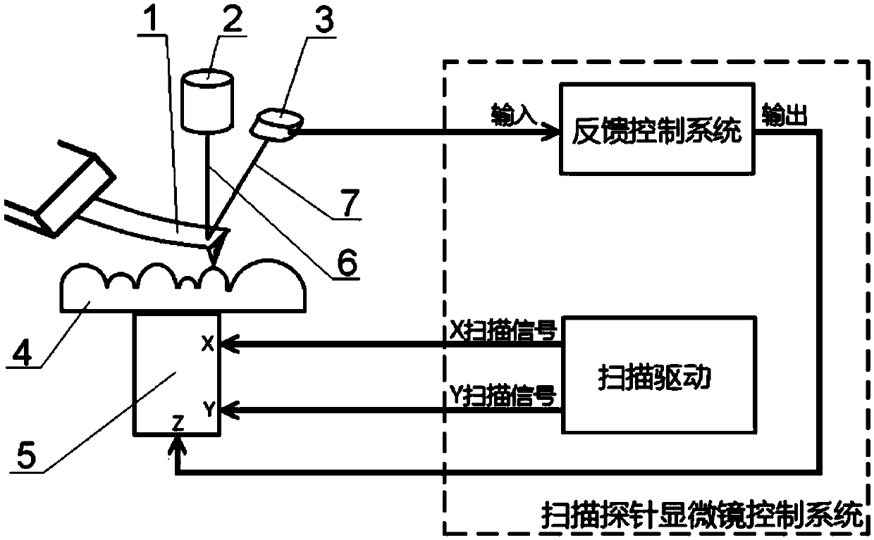
[0018] 1) The existing three types of scanning probe microscopes based on the probe movement mode all need to introduce new optical elements or optical systems (reflector group of scheme 1, incident optical system and reflective optical system of scheme 2, and reflective optical system of scheme 3). Collimating lens, converging lens and imaging lens) to completely decouple the two motion modes of probe bending and probe lifting on the detection signal, the structure is complex and the cost is high
[0019] 2) In addition to controlling the lifting of the probe, the scanning drive devices of the existing three types of scanning probe microscopes based on the probe movement mode also drive other related components to move synchronously (the four-quadrant receiver of the scheme 1, the incident beam of the scheme 2 The optical system, the converging lens of scheme 3), increases the actual load of the scanning drive device, reduces the response frequency of the scanning drive device, and is not conducive to the system to realize the function of fast scanning imaging

Method used


Image

  • A novel scanning probe microscope detection method and system
  • A novel scanning probe microscope detection method and system
  • A novel scanning probe microscope detection method and system

Examples


Embodiment 1

[0097] Aiming at the problem that new optical elements or optical systems need to be introduced in the prior art and the actual load of the scanning drive device will be increased, the present invention proposes a novel scanning probe microscope detection method and system.

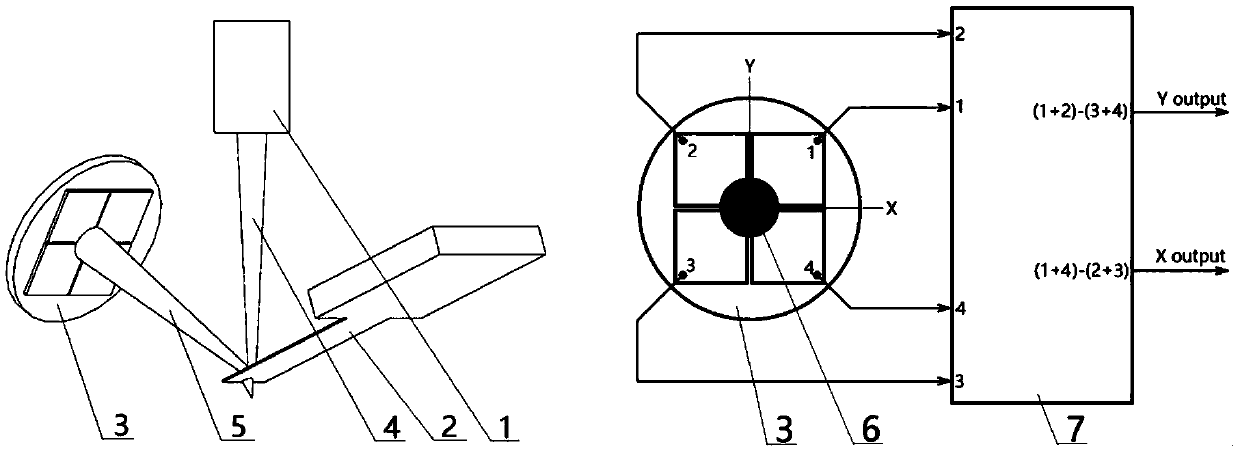
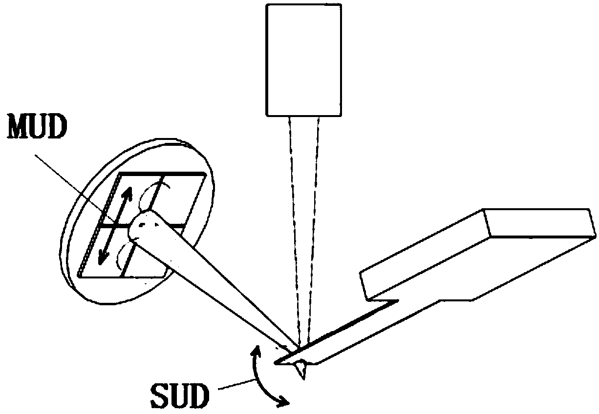
[0098] Such as Figure 12 As shown, this embodiment proposes a scanning probe microscope implementation of a new probe movement mode, without adding any optical system or components, by changing the spatial position of the laser and the four-quadrant receiver, the central axis of the incident laser beam 1. The plane where the central axis of the reflected laser beam is located is perpendicular to the extension axis of the cantilever beam of the micro-cantilever probe, so as to achieve the purpose of completely decoupling the detection signals of the two motion modes of the probe bending and the probe lifting. Figure 12 (a), (b), (c) and (d) are three-dimensional perspective view, top view, front view and...


PUM


Abstract

The invention provides a novel scanning probe microscope detecting method and system. The system comprises a light source, a micro-cantilever probe, a four-quadrant receiver and a receiver signal processing module. The incident light emitted by the light source is reflected by the micro-cantilever probe to form reflected light. The reflected light is received by the four-quadrant receiver. The output end of the four-quadrant receiver is connected with the input end of the receiver signal processing module. The position where the light source and the four-quadrant receiver are adjusted and fixed can make the plane of the central axis of the incident light and the central axis of the reflected light perpendicular to the cantilever beam extension axis of the micro-cantilever probe. According to the invention, the plane of the central axis of the incident light and the central axis of the reflected light is perpendicular to the cantilever beam extension axis of the micro-cantilever probe; two kinds of motion modes such as probe bending and probe lift are fully decoupled on a detection signal; the structure is simple; the cost is low; and the micro-cantilever probe is used as the only load, which ensures the response frequency of a scanning drive. The novel scanning probe microscope detecting method and system can be widely applied to the technical field of microscopes.

Description

technical field [0001] The invention relates to the technical field of microscopes, in particular to a detection method and system for a novel scanning probe microscope. Background technique [0002] Since the appearance of the scanning tunneling microscope (STM) in 1982, a series of new microscopy techniques with similar working principles have been developed, including atomic force microscopy (AFM), lateral force microscopy (LFM), magnetic force microscopy (MFM), static Electric force microscopy (EFM), near-field optical microscopy (SNOM), piezoelectric force microscopy (PFM), scanning probe acoustic microscopy (SPAM), etc., because they all use probes to scan the sample to be tested, while detecting The interaction between the probe and the sample (such as the interaction force between the sample and the probe, etc.), and the related properties of the sample (such as morphology, friction, magnetic domain structure, etc.) are obtained, so it is collectively called scanning...

Claims


Application Information

Patent Timeline
Patent Type & Authority Patents(China)
IPC IPC(8): G01Q30/04
CPCG01Q30/04
Inventor 吴浚瀚
Owner BEING NANO INSTR LTD
Learn More