A cable fixing device and a power distribution cabinet using the cable fixing device

A technology for fixing devices and cables, which is applied in the substation/power distribution device shell, substation/switch layout details, electrical components, etc., which can solve the problems of cumbersome and complicated operation process, low work efficiency, and poor versatility of hoop, and achieve easy use , Simple process, strong versatility

Active Publication Date: 2018-10-30
HENAN SENYUAN ELECTRIC CO LTD
View PDF13 Cites 0 Cited by
  • Summary
  • Abstract
  • Description
  • Claims
  • Application Information

AI Technical Summary

Problems solved by technology

It is necessary to tighten bolts when disassembling and installing cables, especially in the case of multiple cables, it is necessary to tighten a large number of bolts, resulting in cumbersome and complicated operation process, low work efficiency, high labor intensity for operators, and when faced with different When the diameter of the cable is small, the versatility of the hoop is poor, and the hoop needs to be replaced, resulting in poor versatility of the fixing device and inconvenient use
[0003] The Chinese utility model patent with the authorized announcement number CN 201726077 U discloses a cable fixing device, which uses a pressure plate to fix the cable on the angle steel. Or loosen the cable, which saves a lot of steps of screwing, but when faced with cables of different thicknesses, the cables will have different degrees of radial deflection under the action of the pressure plate, and the cables will produce an axial deflection in the axial direction. traction, which can damage the cable or cause the cable's connector to be loosely connected

Method used


Image

  • A cable fixing device and a power distribution cabinet using the cable fixing device
  • A cable fixing device and a power distribution cabinet using the cable fixing device
  • A cable fixing device and a power distribution cabinet using the cable fixing device

Examples


Embodiment Construction

[0036] The embodiments of the present invention will be further described below in conjunction with the drawings.

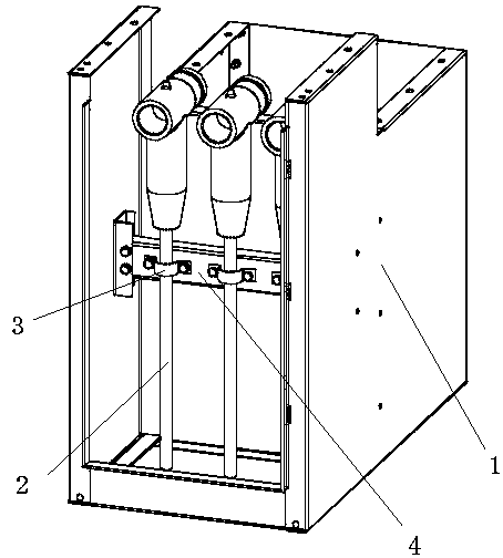
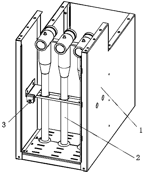
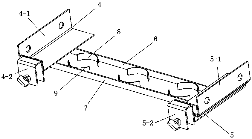
[0037] A specific embodiment of a power distribution cabinet of the present invention, such as Figure 2 to Figure 12 As shown, it includes a cabinet 1 and a cable fixing device 3 arranged in the cabinet 1. The cable fixing device 3 includes a base. The base includes a first base 4 and a second base 5 correspondingly arranged on opposite side walls. The first base 4 includes a first mounting plate 4-1, a first guide rail 4-3 and a first U-shaped plate 4-2, the second base 5 includes a second mounting plate 5-1, a second guide rail 5-3 and a second U-shaped The plate 5-2, the first mounting plate 4-1 and the second mounting plate 5-1 are all connected to the corresponding side walls of the cabinet 1 by bolts, and the first guide rail 4-3 is welded to the first mounting plate 4-1 The second guide rail 5-3 is welded to the lower surface of the second mounting plate 5-...


PUM


Abstract

The invention relates to a cable fixing device and a power distribution cabinet using the same. The cable fixing device comprises a base, and a first mounting beam and a second mounting beam arranged on the base side by side at intervals. The first mounting beam is provided with a first clamping structure. A second clamping structure is arranged on the second mounting beam. The mounting beams are movably mounted on the base through mounting structures so that the first and second mounting beams can achieve relative motion. The base is further provided with a driving mechanism used for driving the first mounting beam and the second mounting beam to move towards or backwards to adjust the distance therebetween. When cables are required to be uninstalled or installed, so long as the distance between the first mounting beam and the second mounting beam is adjusted by the driving mechanism, the respective mounting beams can move towards or backwards. Thus, when cables with different thicknesses are fixed, it can be guaranteed that the cable cannot deflected in the radial direction seriously and it can be avoided that axial traction is generated on the cables so as to cause damage to the cables or cable connectors.

Description

Technical field [0001] The invention relates to the field of equipment used in power systems, in particular to a cable fixing device and a power distribution cabinet using the cable fixing device. Background technique [0002] In the power distribution cabinet of the power system, the cable plays a vital role as a part of its internal inlet and outlet ends. When the cables are installed in the power distribution cabinet, they usually need to be fixed to prevent safety accidents. The existing cable fixing methods mostly use such as figure 1 As shown in the fixing method, the cabinet 1 of the power distribution cabinet is provided with a supporting beam 4, the cable 2 is fixed to the supporting beam 4 through a clamping plate 3, and both ends of the clamping plate 3 are connected to the supporting beam 4 by screws. In the prior art, there is also a hoop method for fixing cables. For example, the new type of cable fixing device disclosed in the Chinese Utility Model Patent with Aut...

Claims


Application Information

Patent Timeline
Patent Type & Authority Patents(China)
IPC IPC(8): H02G3/02H02B1/30H02B1/20
CPCH02B1/202H02B1/30H02G3/02
Inventor 范冠鹏刘洋宋浩李金辉潘亚培
Owner HENAN SENYUAN ELECTRIC CO LTD
Why Eureka
Try Eureka