A composite shaft

A shaft and axial technology, applied in the field of torque transmission structure, can solve problems such as product control failure, damage, cable damage, etc., to avoid product cable damage and improve experience.

Inactive Publication Date: 2017-03-15
HUIZHOU TCL MOBILE COMM CO LTD
View PDF5 Cites 0 Cited by
  • Summary
  • Abstract
  • Description
  • Claims
  • Application Information

AI Technical Summary

Problems solved by technology

[0002] With the rapid development of electronic device technology, wearable devices have gradually become a relatively popular electronic product in the market. However, wearable devices generally install cables or other connecting lines inside the product. When bent or twisted, the internal cable will be damaged, causing product control failure or damage, and the user experience of the product will be greatly reduced

Method used


Image

  • A composite shaft
  • A composite shaft
  • A composite shaft

Examples


Embodiment 1

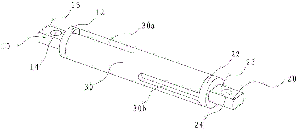
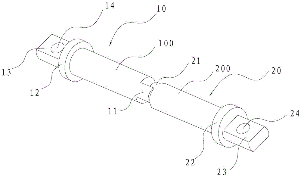
[0023] refer to figure 1 and figure 2 , the composite rotating shaft of the embodiment of the present invention includes a first rotating shaft 10, a second rotating shaft 20 and a sleeve 30, one end face of the first rotating shaft 10 and one end face of the second rotating shaft 20 are arranged oppositely, and the first rotating shaft 10 and the second rotating shaft The two opposite end faces of 20 are protrudingly provided with a first shaft head 11 and a second shaft head 21, and the first shaft head 11 and the second shaft head 21 have intervals in the circumferential direction for connecting the first rotating shaft 10 and the second shaft head. When the two rotating shafts 20 are relatively rotating around the circumference, they cooperate to limit the relative rotation angle between the first rotating shaft 10 and the second rotating shaft 20 .

[0024] By setting the sleeve 30, the first rotating shaft 10 and the second rotating shaft 20 are limited, so as to ensur...

Embodiment 2

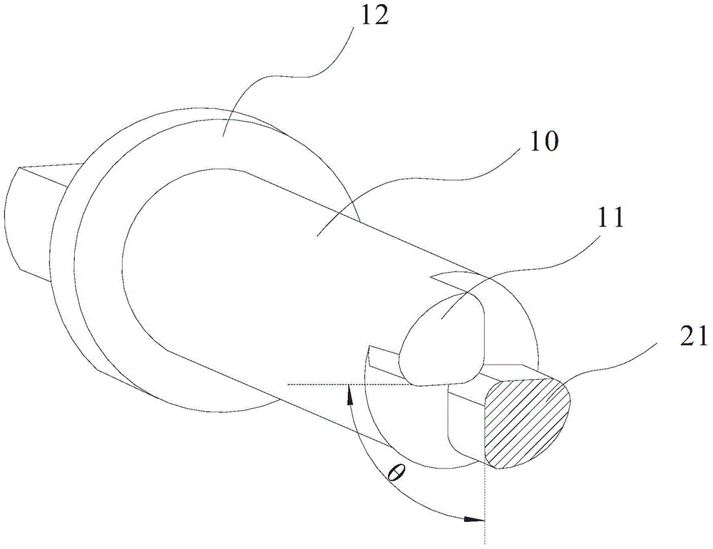
[0036] Such as Figure 4 As shown, it is a schematic diagram of the cross-sectional structure of the composite rotating shaft of this embodiment. The difference from Embodiment 1 is that there are multiple first shaft heads 11 and second shaft heads 21, and the centers of the first shaft 10 and the second shaft The center of the rotating shaft 20 is the center of the circle and is evenly arranged on the circumference, and the first shaft head 11 and the second shaft head 21 are arranged at intervals. The angle θ1 between the first shaft head 11 and the second shaft head 21 can be set according to actual rotation needs. By setting more shaft heads on the shaft, the contact area when the two shafts rotate is further increased, effectively dispersing the stress generated during the rotation process, and protecting the shaft head structure.

Embodiment 3

[0038] This embodiment also provides a wearable device, the wearable device at least includes two first connectors (not shown) and second connectors (not shown) connected to each other, the first connector and A connecting line is provided between the second connecting parts, and the first connecting part is connected to the second connecting part by the composite rotating shaft described in any one of the previous embodiments.


PUM


Abstract

The invention discloses a composite rotating shaft, which comprises a first rotating shaft, a second rotating shaft and a sleeve, a transverse plane of the first rotating shaft and a transverse plane of the second rotating shaft are oppositely arranged and inserted in the sleeve, a first shaft head and a second shaft head are arranged on two transverse planes of the first rotating shaft and the second rotating shaft, the first shaft head and the second shaft head are used for cooperating for limiting an angle which can be relatively rotated between the first rotating shaft and the second rotating shaft when the first rotating shaft and the second rotating shaft are relatively rotated by winding the circumferential direction. According to the invention, the composite rotating shaft is designed, the first rotating shaft and the second rotating shaft enable slight rotation in a certain angle scope, flat cable damage of product due to unexpected wide-angle folding or distortion of the product can be avoided, and experience of the user can be enhanced.

Description

technical field [0001] The invention relates to a torsion transmission structure, in particular to a compound rotating shaft. Background technique [0002] With the rapid development of electronic device technology, wearable devices have gradually become a relatively popular electronic product in the market. However, wearable devices generally install cables or other connecting lines inside the product. When bent or twisted, the internal cable will be damaged, causing product control failure or damage, and the user experience of the product will be greatly reduced. Contents of the invention [0003] In view of the deficiencies in the prior art, the present invention provides a composite rotating shaft that can avoid damage to the product caused by accidental large-angle turning or twisting. [0004] In order to achieve the above object, the present invention adopts the following technical solutions: [0005] A composite rotating shaft, comprising a first rotating shaft, ...

Claims


Application Information

Patent Timeline
Patent Type & Authority Patents(China)
IPC IPC(8): F16C11/04
Inventor 刘殷
Owner HUIZHOU TCL MOBILE COMM CO LTD
Why Eureka
Try Eureka