Dispensing equipment for floodlight production

A technology for lighting and dispensing, which is applied to devices and coatings that apply liquid to the surface, which can solve the problem of low dispensing quality, difficulty in controlling the point contest and dispensing position, and inability to control the amount of dispensing and dispensing. Dispensing position and other issues to achieve the effect of improving the scope of use

Inactive Publication Date: 2017-08-25
GRACE(NINGBO) LIGHTING CO LTD
View PDF0 Cites 7 Cited by
  • Summary
  • Abstract
  • Description
  • Claims
  • Application Information

AI Technical Summary

Problems solved by technology

Especially in the field of lighting, there are all kinds of lighting lamps on the market. The lighting lamps need to be dispensed during the production process. The current dispensing equipment cannot control the amount and position of dispensing well, resulting in low quality
[0003] To sum up, at present, it is necessary to develop a kind of dispensing equipment for lighting production that can effectively control the dispensing amount and dispensing position, so as to overcome the shortcomings of the existing technology that it is difficult to control the point contest and dispensing position.

Method used


Image

  • Dispensing equipment for floodlight production
  • Dispensing equipment for floodlight production
  • Dispensing equipment for floodlight production

Examples


Embodiment 1

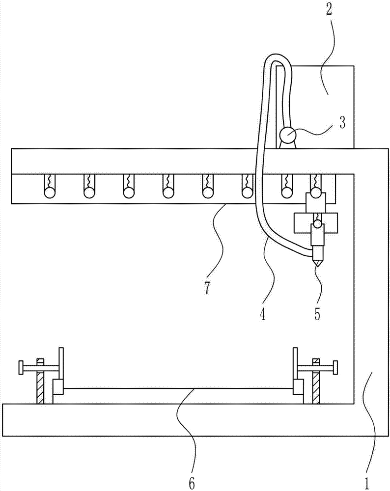
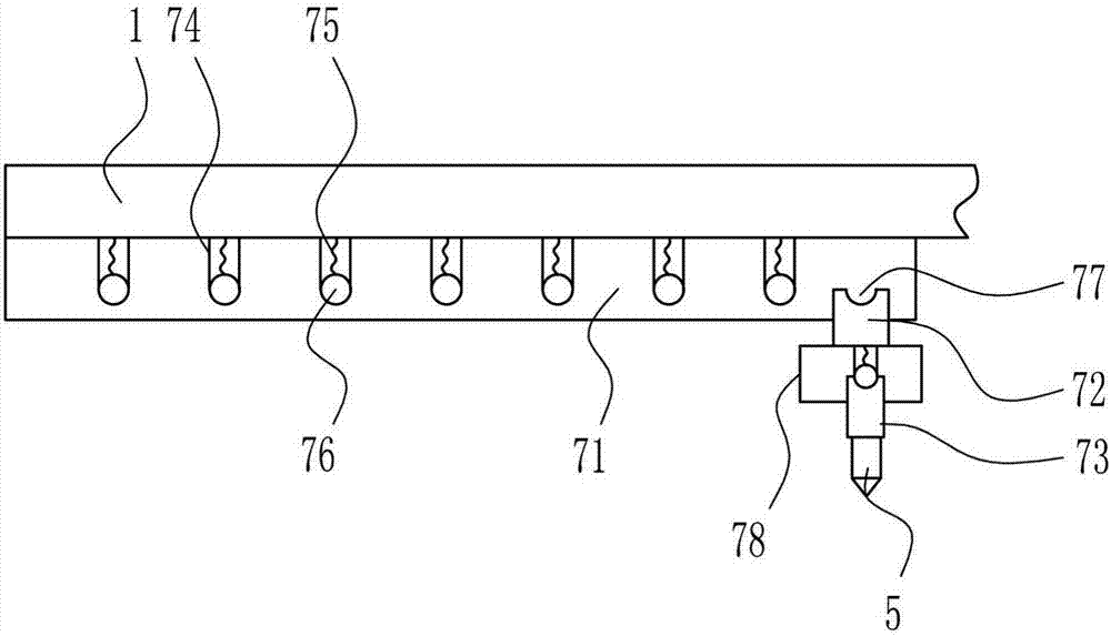
[0030] A kind of dispensing equipment for lighting production, such as Figure 1-6 As shown, it includes a mounting frame 1, a material storage box 2, a booster pump 3, a hose 4, a dispensing head 5, a fixing device 6 and a position adjustment device 7, and the bottom of the mounting frame 1 is provided with a fixing device 6, and the mounting frame 1 There is a material storage box 2 on the right side of the top, a pressure pump 3 is provided on the left side of the inner bottom of the material storage box 2, a hose 4 is connected to the pressure pump 3, and a position adjustment device 7 is installed on the top of the installation frame 1. A dispensing head 5 is provided at the bottom of the adjusting device 7 , and the hose 4 passes through the material storage box 2 and is connected with the dispensing head 5 .

Embodiment 2

[0032] A kind of dispensing equipment for lighting production, such as Figure 1-6 As shown, it includes a mounting frame 1, a material storage box 2, a booster pump 3, a hose 4, a dispensing head 5, a fixing device 6 and a position adjustment device 7, and the bottom of the mounting frame 1 is provided with a fixing device 6, and the mounting frame 1 There is a material storage box 2 on the right side of the top, a pressure pump 3 is provided on the left side of the inner bottom of the material storage box 2, a hose 4 is connected to the pressure pump 3, and a position adjustment device 7 is installed on the top of the installation frame 1. A dispensing head 5 is provided at the bottom of the adjusting device 7 , and the hose 4 passes through the material storage box 2 and is connected with the dispensing head 5 .

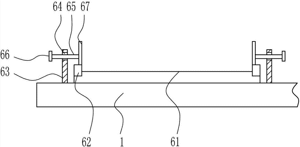
[0033] The fixing device 6 includes a first slide rail 61, a first slide block 62, a vertical plate 63, a bolt 65, a runner 66 and a pressing plate 67. The bottom...

Embodiment 3

[0035] A kind of dispensing equipment for lighting production, such as Figure 1-6 As shown, it includes a mounting frame 1, a material storage box 2, a booster pump 3, a hose 4, a dispensing head 5, a fixing device 6 and a position adjustment device 7, and the bottom of the mounting frame 1 is provided with a fixing device 6, and the mounting frame 1 There is a material storage box 2 on the right side of the top, a pressure pump 3 is provided on the left side of the inner bottom of the material storage box 2, a hose 4 is connected to the pressure pump 3, and a position adjustment device 7 is installed on the top of the installation frame 1. A dispensing head 5 is provided at the bottom of the adjusting device 7 , and the hose 4 passes through the material storage box 2 and is connected with the dispensing head 5 .

[0036] The fixing device 6 includes a first slide rail 61, a first slide block 62, a vertical plate 63, a bolt 65, a runner 66 and a pressing plate 67. The bottom o...


PUM


Abstract

The invention relates to a glue dispensing device, in particular to a glue dispensing device for lighting lamp production. The technical problem to be solved by the present invention is to provide a kind of dispensing equipment for lighting production which can effectively control the dispensing amount and dispensing position. In order to solve the above technical problems, the present invention provides such a dispensing equipment for lighting production, including a mounting frame, etc.; a fixing device is provided at the bottom of the mounting frame; There is a booster pump on the left side of the inner bottom, and a hose is connected to the booster pump. A position adjustment device is installed on the top of the installation frame, and a dispensing head is installed at the bottom of the position adjustment device. The hose passes through the storage box and the dispensing head. connect. The present invention can dispens glue at different positions through the position adjustment device, and the arrangement of the first spring and the steel ball cooperates with the first arc-shaped groove, so that the second slider and the third slider each reach a hollow column.

Description

technical field [0001] The invention relates to a glue dispensing device, in particular to a glue dispensing device for lighting lamp production. Background technique [0002] With the progress and development of society, people's living standards have gradually improved, and people's lifestyles have also undergone great changes. People have high requirements for their quality of life. Especially in the field of lighting, there are all kinds of lighting lamps on the market. The lighting lamps need to be dispensed during the production process. The current dispensing equipment cannot control the amount and position of dispensing well, resulting in low quality. [0003] To sum up, it is necessary to develop a dispensing equipment for lighting production that can effectively control the dispensing amount and dispensing position, so as to overcome the shortcomings of the existing technology that it is difficult to control the dispensing amount and dispensing position. Content...

Claims


Application Information

Patent Timeline
Patent Type & Authority Applications(China)
IPC IPC(8): B05C5/02B05C11/10B05C13/02
CPCB05C5/0208B05C11/1002B05C13/02
Inventor 张晓艳
Owner GRACE(NINGBO) LIGHTING CO LTD
Why Eureka
Try Eureka