Hydraulic coded lock using cipher key to unlock

A coded key and coded lock technology, applied in coded locks, keys, building locks, etc., can solve problems such as difficulty in key positioning, lack of precise positioning control of coded valve spool, and difficult assembly

Inactive Publication Date: 2013-10-02
周跃平
View PDF1 Cites 3 Cited by
  • Summary
  • Abstract
  • Description
  • Claims
  • Application Information

AI Technical Summary

Problems solved by technology

[0002] There is an application number of 201120387911.6 in the technical scheme of the existing key-controlled hydraulic combination lock. The disadvantages of this scheme are: the lack of precise positioning control of the spool of the combination valve when the lock is unlocked, the detailed technical structure of the password automatically disrupted when the key is drawn out, and the password large lock size
The key position of the key is used to control the movement stroke of the spool of the coded valve. Since the spool of the coded valve belongs to precise positioning movement to control the opening and closing of the oil passage, when unlocking, the distance between the key and the coded valve must be accurately positioned. Each key position and each spool of the password valve can be positioned accurately, and the spool of the password valve can realize precise positioning movement. This scheme only provides a basic structure of the key hole, and it is difficult to realize the positioning of the key only by the key hole, and even the original configuration may appear. The key cannot unlock the lock; the key of the hydraulic combination lock only provides the password information required for unlocking. When the hydraulic combi

Method used


Image

  • Hydraulic coded lock using cipher key to unlock
  • Hydraulic coded lock using cipher key to unlock
  • Hydraulic coded lock using cipher key to unlock

Examples


Embodiment 1

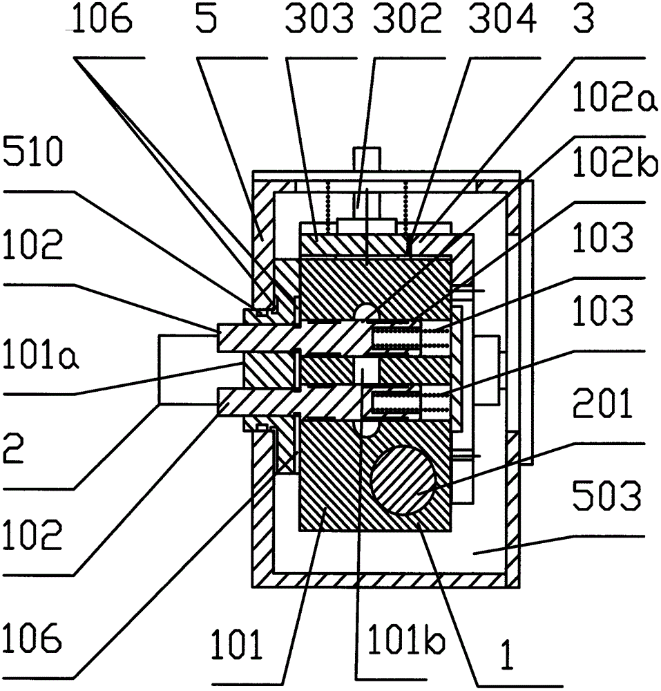
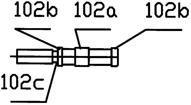
[0092]Embodiment 1 includes a lock body mechanism 5, a combination valve 1, a power unit 2, and a lock bolt mechanism 3. The power unit 2 includes a manual oil pump 201. The lock bolt mechanism 3 includes an oil cylinder 302. The lock body mechanism 5 includes a working The medium box 503 and the sealing ring 510 are formed. The working medium box 503 is located at the bottom of the lock body mechanism 5. The password valve 1 includes four spools 102 and four spool positioning springs 103 and are integrally assembled on the same valve body 101, which can Effectively reduce the volume and manufacturing cost of the hydraulic combination lock, which is convenient for the key to be miniaturized and carried by people; The position of the control key is in contact with the key positioning platform 101a, so that when the key is unlocked each time, the movement of the spool 102 compresses the spool positioning spring 103, and the active force of the spool positioning spring 103 prevent...


PUM


Abstract

The invention relates to a hydraulic coded lock using a cipher key to unlock in the field of security and protection. The hydraulic coded lock comprises a lock body mechanism, a lock latch mechanism, a coded valve and a power unit. The lock body mechanism comprises a working medium box. The lock latch mechanism comprises an oil cylinder. The power unit comprises a manual oil pump, wherein the manual oil pump, the coded valve and the oil cylinder are connected through oil ducts. The lock latch mechanism, the manual oil pump and the coded valve are assembled on the lock body mechanism. The hydraulic coded lock is characterized in that the coded valve comprises two or more than two valve elements and two or more than two valve element locating springs, wherein the valve elements and the valve element locating springs are integrally assembled on the same valve body; one ends of the valve element locating springs are assembled on the valve elements; the coded valve is provided with a key locating platform which is used for directly limiting the position of a key in the unlocking process or indirectly limiting the position of the key in the unlocking process through location fit between the key locating platform and the lock body mechanism. The hydraulic coded lock is small in size and novel in concept, and has high innovativeness and practical value. The key and the coded valve are accurately matched, and a password can be automatically disorganized when the key is moved away.

Description

technical field [0001] The invention relates to a hydraulic combination lock which is mainly used in some fixed places in the security field, such as anti-theft doors and safes, and is unlocked by a combination key. Background technique [0002] There is an application number of 201120387911.6 in the technical scheme of the existing key-controlled hydraulic combination lock. The disadvantages of this scheme are: the lack of precise positioning control of the spool of the combination valve when the lock is unlocked, the detailed technical structure of the password automatically disrupted when the key is drawn out, and the password The lock is bulky. The key position of the key is used to control the movement stroke of the spool of the coded valve. Since the spool of the coded valve belongs to precise positioning movement to control the opening and closing of the oil passage, when unlocking, the distance between the key and the coded valve must be accurately positioned. Each ...

Claims


Application Information

Patent Timeline
IPC IPC(8): E05B51/02E05B15/00E05B19/18E05B37/20E06B5/11E05B65/52A47B96/00
Inventor 周跃平尹雄鹰周文珺
Owner 周跃平
Why Eureka
Try Eureka