Milling and turning composite electric spindle assembly and corresponding numerical control machining equipment

An electric spindle and spindle technology, applied in the field of CNC machine tools, can solve problems such as high maintenance or maintenance costs, affecting continuous production, and reducing service life, and achieving reduced maintenance or maintenance costs, good protection effect, and long service life. Effect

Inactive Publication Date: 2020-09-18
北京东方精益机械设备有限公司
View PDF5 Cites 3 Cited by
  • Summary
  • Abstract
  • Description
  • Claims
  • Application Information

AI Technical Summary

Problems solved by technology

[0002] The braking mechanism of the milling and turning compound electric spindle of the traditional CNC machining equipment is usually set at the rear end of the spindle, which is far away from the cutting point. It is required that the spindle must have sufficient rigidity to prevent excessive torque deformation during braking, but in practice In application, due to frequent braking and high-precision cutting requirements, frequent deformation or damage of the spindle cannot be avoided, resulting in high repair or maintenance costs and affecting machining accuracy
In addition, the traditional milling and turning combined electric spindle usually adopts a rigid tool loosening method. When the tool is released, the bearing of the spindle bears a large axial force. Frequent movements will easily cause damage to the bearing of the spindle, reduce the service life, and affect the continuous production.

Method used


Image

  • Milling and turning composite electric spindle assembly and corresponding numerical control machining equipment
  • Milling and turning composite electric spindle assembly and corresponding numerical control machining equipment
  • Milling and turning composite electric spindle assembly and corresponding numerical control machining equipment

Examples


Embodiment Construction

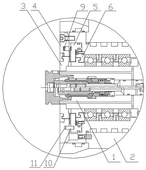
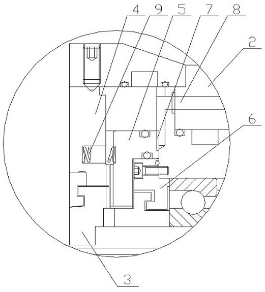
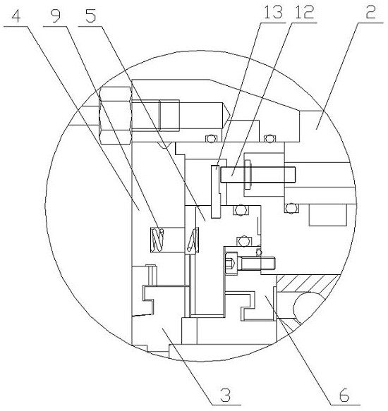
[0032] see Figure 1 to Figure 7, the present invention discloses a milling and turning composite electric spindle assembly, which includes a spindle 1 and a spindle housing (components containing the housing) 2, and also includes a spindle brake mechanism, which is arranged on the spindle The front end of the front end includes a rotating toothed plate 3, a positioning toothed plate 4 and a moving toothed plate 5. The rotating toothed plate 3, the positioning toothed plate 4 and the moving toothed plate 5 are all annular, and their central axes are all located on the axis of the main shaft. A three-gear mechanism is formed. The rotating toothed disc is coaxially fixed on the front end of the main shaft and rotates synchronously with the main shaft. The positioning toothed disc is coaxially sleeved on the outside of the rotating toothed The housings are fixed together, and there is a rotation gap between the inner circle and the outer circle of the rotating toothed disc. The p...


PUM


Abstract

The invention relates to a milling and turning composite electric spindle assembly and numerical control machining equipment. The milling and turning composite electric spindle assembly comprises a spindle, a spindle shell and a spindle braking mechanism. The spindle braking mechanism comprises a rotary toothed disc, a positioning toothed disc and a movable toothed disc, the rotary toothed disc coaxially and fixedly sleeves the front end of the spindle, the positioning toothed disc coaxially sleeves the outer side of the rotary toothed disc and is provided with a rotating clearance, the positioning toothed disc is fixedly connected to the front end of the spindle shell, the movable toothed disc is mounted between the spindle shell and a front bearing flange in a sleeving mode and is slidably and hermetically matched with the spindle shell and the front bearing flange, an annular oil cavity is formed in the rear surface of the movable toothed disc, the structure and number of end teethof each toothed disc are the same, the end teeth of the rotary toothed disc and the positioning toothed disc are located on the rear end surface, and the end teeth of the movable toothed disc are located on the front end surface. The spindle braking mechanism is installed at the front end of the spindle and is close to a cutting point, the braking effect is good, the torque applied to the spindleis small during braking, so that the spindle meets the braking requirement without particularly large rigidity, and the deformation damage of the spindle caused by frequent braking can be effectivelyavoided.

Description

technical field [0001] The invention relates to a milling and turning composite electric spindle assembly and numerical control machining equipment, belonging to the field of numerical control machine tools. Background technique [0002] The braking mechanism of the milling and turning compound electric spindle of the traditional CNC machining equipment is usually set at the rear end of the spindle, which is far away from the cutting point. It is required that the spindle must have sufficient rigidity to prevent excessive torque deformation during braking, but in practice In application, due to frequent braking and high-precision cutting requirements, frequent deformation or damage of the spindle cannot be avoided, resulting in high repair or maintenance costs and affecting machining accuracy. In addition, the traditional milling and turning combined electric spindle usually adopts a rigid tool loosening method. When the tool is released, the bearing of the spindle bears a l...

Claims


Application Information

Patent Timeline
Patent Type & Authority Applications(China)
IPC IPC(8): B23B19/02B23Q3/18B23Q5/20
CPCB23Q1/70B23Q5/20B23Q3/18
Inventor 李南京
Owner 北京东方精益机械设备有限公司
Why Eureka
Try Eureka