A joint connection method of vertical prefabricated components

A vertical component and node connection technology, applied in the direction of building structure, construction, etc., can solve the problems of difficult to guarantee construction quality, high construction cost and high process requirements, and achieve a simplified way of precast concrete vertical prefabricated component node connection, Improve construction quality and strengthen the effect of overall connection

Active Publication Date: 2019-11-19
GUANGDONG PROVINCIAL ACAD OF BUILDING RES GRP CO LTD
View PDF7 Cites 0 Cited by
  • Summary
  • Abstract
  • Description
  • Claims
  • Application Information

AI Technical Summary

Problems solved by technology

However, this method has the following defects: the steel bars of the upper vertical prefabricated components are connected by sleeve grouting. Although the effective transmission of the strength of the steel bars can be guaranteed, during the construction process, the process of aligning the steel bars with the sleeves and the subsequent grouting The requirements are high, the process is very cumbersome, and the construction quality is difficult to guarantee. In addition, the construction cost is relatively high

Method used


Image

  • A joint connection method of vertical prefabricated components
  • A joint connection method of vertical prefabricated components
  • A joint connection method of vertical prefabricated components

Examples


Embodiment 1

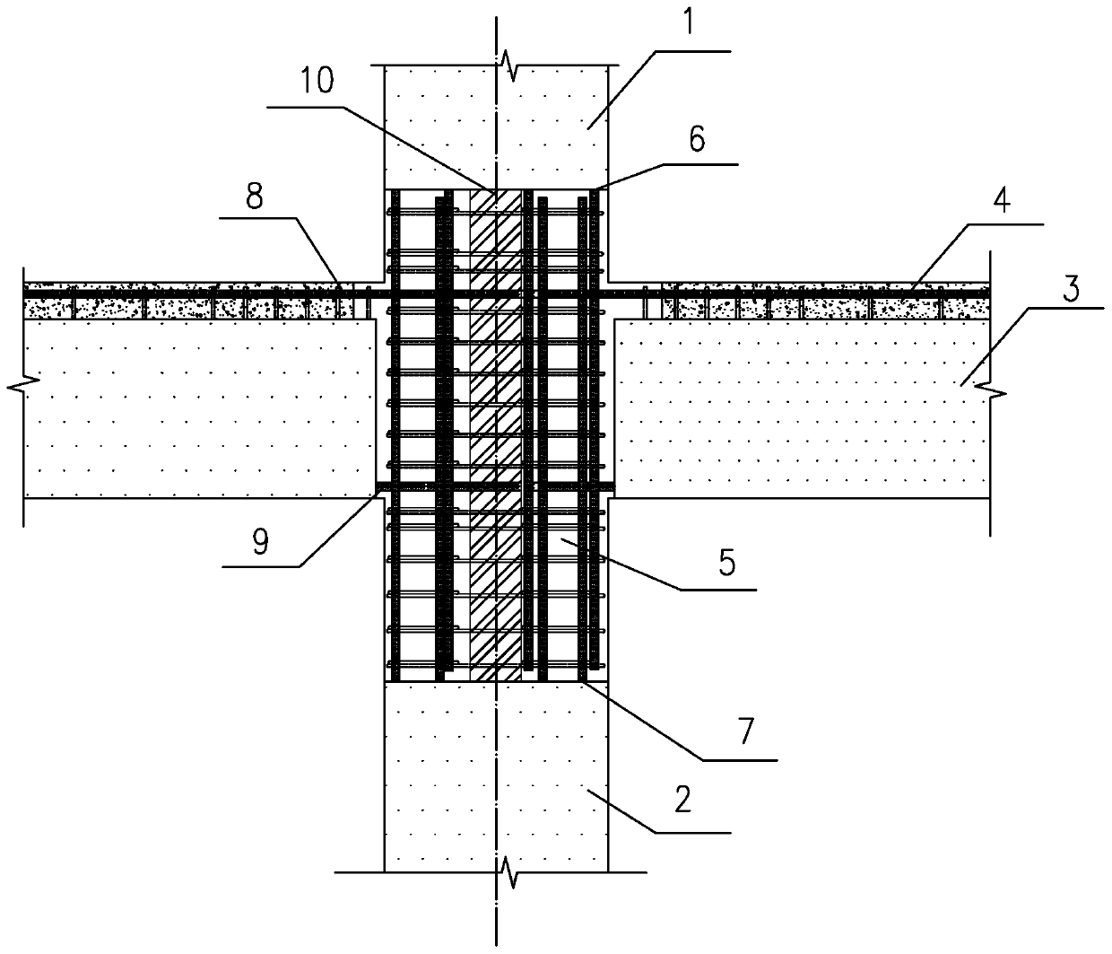
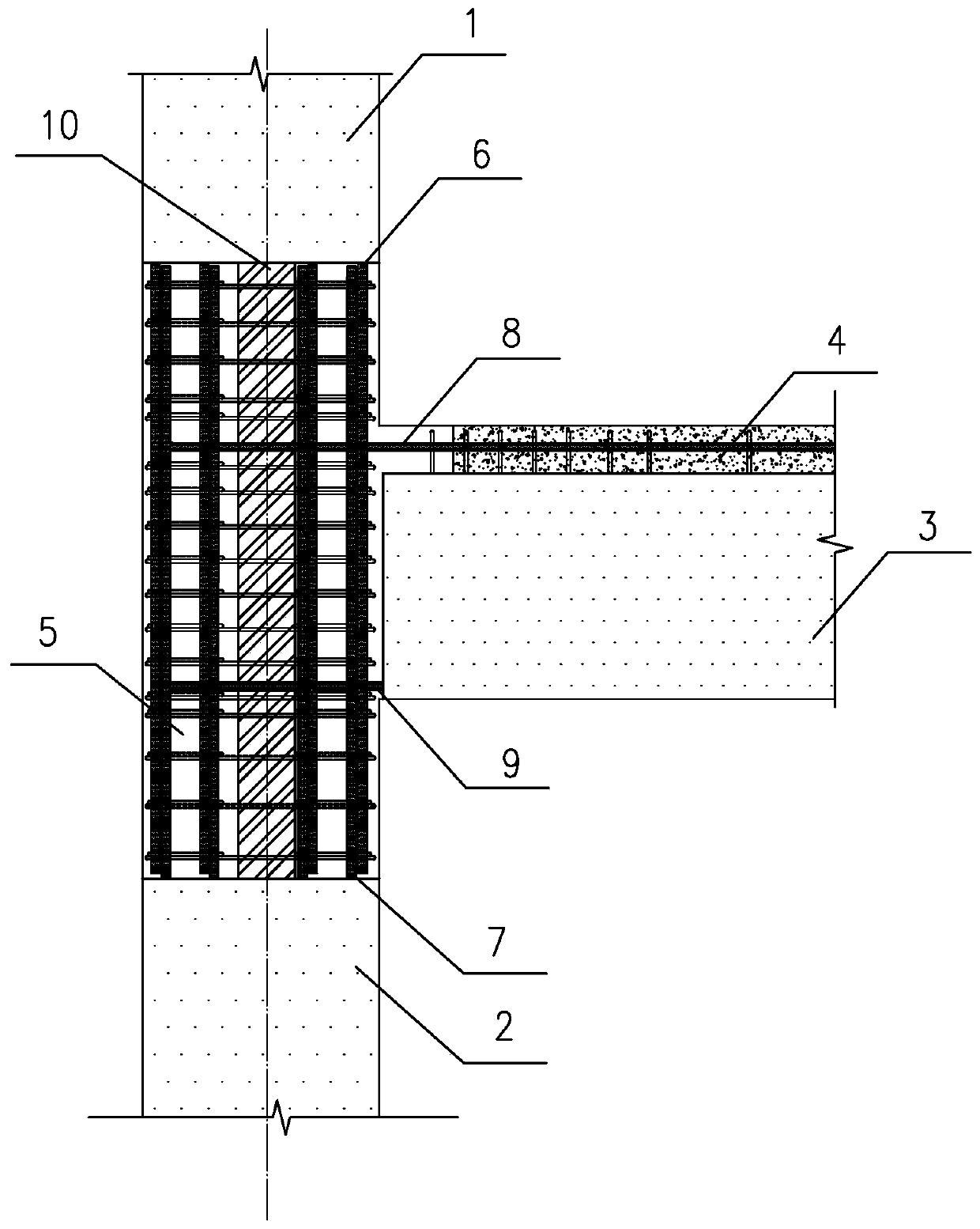
[0024] Such as figure 1 and 2 As shown, in this embodiment, the precast concrete horizontal component is a precast concrete composite beam slab 3, and the precast concrete vertical component is a precast concrete frame column, that is, the upper precast concrete frame column 1 and the lower precast concrete frame column 2. The nodes of an embodiment are frame column mid-level nodes.

[0025] A novel vertical prefabricated member node connection method specifically includes the following steps:

[0026] (1) Hoist the precast concrete composite beam slab 3 to the installation position, bind the gluten 8 of the precast concrete composite beam slab 3 on the upper surface of the precast concrete composite beam slab 3, adjust the bottom rib 9 of the precast concrete composite beam slab 3 and the The positions of the longitudinal reinforcement 7 of the concrete frame column 2 and the longitudinal reinforcement 6 of the upper precast concrete frame column 1. The anchorage length of...

Embodiment 2

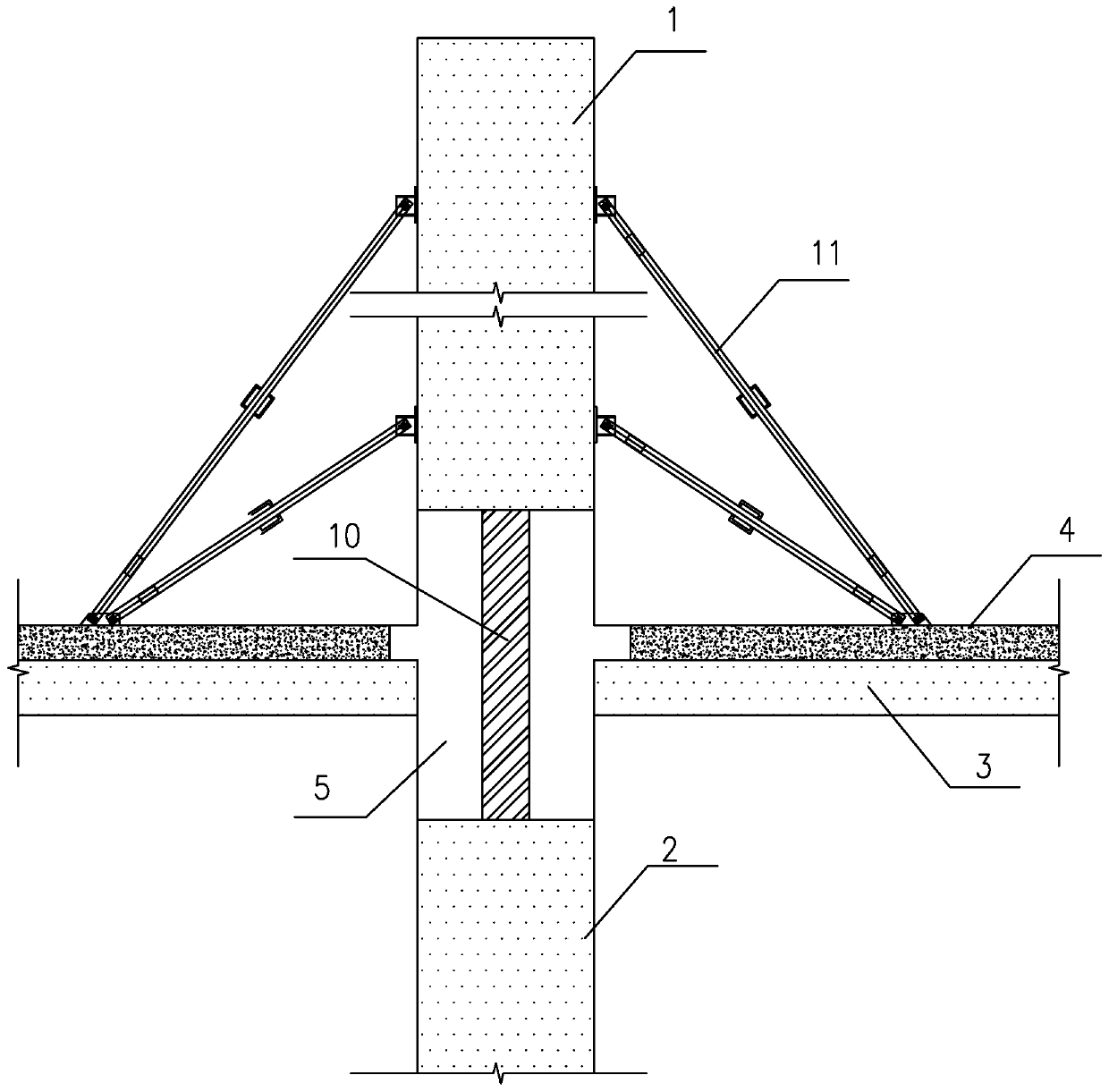
[0031] Such as image 3 As shown, the difference between this embodiment and Embodiment 1 is that the node of this embodiment is the edge node of the middle layer of the frame column. From a structural comparison, except for the reduction of the one-time concrete pouring area 4, the construction steps of this embodiment are the same as those of the implementation The construction steps of Example 1 are exactly the same.


PUM


Abstract

The invention discloses a novel vertical prefabricated part joint connecting method. The method includes the steps that 1, a prefabricated concrete horizontal member is hoisted to an installation position and bundled with ribs; 2, first concrete pouring is conducted, and a space used for secondary concrete pouring is reserved in a joint region; 3, an upper-layer prefabricated concrete vertical member is hoisted to an installation position, and a support steel truss embedded in the upper-layer prefabricated concrete vertical member in advance and stretching out of the lower end of the upper-layer prefabricated concrete vertical member is placed on a lower-layer prefabricated concrete vertical member so as to support the upper-layer prefabricated concrete vertical member to make the upper-layer prefabricated concrete vertical member stable; 4, steel bar binding is conducted in the joint region by passing through the support steel truss, formwork supporting is conducted, secondary concrete pouring of the joint region is conducted, and formwork removal is conducted after concrete reaches the design strength. The effective transfer of the steel bar strength and the integrality of the joint region are ensured, the construction process is simplified, construction operation is convenient, the construction quality is improved, the construction costs are saved, the construction time is shortened, and the overall connection between the vertical members is reinforced.

Description

technical field [0001] The invention relates to a node connection method of vertical prefabricated components. Background technique [0002] Prefabricated prefabricated concrete structures are widely used in advanced countries due to their advantages of energy saving, environmental protection, template saving, easy control of component quality, short construction period, labor saving, and little influence of climatic conditions. In recent years, under the premise of the rapid improvement of construction technology and the national development strategy, my country's construction industrialization road has risen again. With the research and vigorous promotion of prefabricated concrete buildings in my country, the design and construction technology of prefabricated concrete structures has developed rapidly. Prefabricated concrete structures are widely used in residential buildings, public buildings and industrial buildings. [0003] Concrete prefabricated structural nodes pla...

Claims


Application Information

Patent Timeline
Patent Type & Authority Patents(China)
IPC IPC(8): E04B1/21E04B1/58
CPCE04B1/21E04B1/58
Inventor 曹大燕徐其功毛娜
Owner GUANGDONG PROVINCIAL ACAD OF BUILDING RES GRP CO LTD
Why Eureka
Try Eureka